
How to 3D Print a Logo: From PNG or SVG to a Print
Give your logo a thickness and a base, then check the lines, colours and scale before it reaches the printer.
You can 3D print a logo without learning Blender. Start with the company, club or team artwork you already have as a PNG, JPG or SVG, then give its outline a physical thickness. The free image to STL converter takes a raster image through that first stage in your browser. You can use the resulting shape for a sign, a badge or a keychain, or combine it with an existing model when the logo belongs on a part.
Decide what the finished object needs to do before converting the file. A desk sign needs a readable face and a way to stand up. A keychain needs a loop that survives being pulled. A stamp needs mirrored artwork and a clear printing surface. A logo pressed into a box needs a recess that leaves enough wall behind it. These choices affect the base, height and orientation much more than the colour of the original image.
For a first project, use a dark, simple logo at 100 mm wide, raise it 3 mm above a 1.5 mm base, and print with the flat back on the bed. Keep the smallest line at least 0.8 mm wide for a typical 0.4 mm nozzle. SVG artwork can also go through a slicer's vector import workflow. A mascot that needs a rounded body, a back and side details belongs in the full 3D workflow later in this guide.
How to Turn a Logo Into a 3D Print, Step by Step
This example makes a small plaque with a raised logo. The target is a 100 mm longest side, a 3 mm extrusion and a 1.5 mm base, giving 4.5 mm total height wherever the logo is raised. Start with a dark silhouette on a transparent background so you can see exactly which shapes become solid. Keep a copy of the original artwork and work on a separate print version if you need to widen a line or remove tiny text.
The six steps below take you from that artwork to a sliced job. You will check the image mask, physical dimensions and layer preview at separate points. Each check catches a different problem: the mask exposes background noise, dimensions reveal weak or undersized details, and preview shows whether those details receive actual extrusion paths. Complete the sequence with one small sample before filling the plate with copies.
Export the logo with a transparent background
Export a PNG at 1024 px or more on its longest side from the original artwork. Make the printable logo dark and leave the background transparent. Crop excess margin while keeping a little space around the outline, and inspect small letter openings at full size. The converter also accepts JPG and WEBP, but PNG makes the separation between the mark and its background easy to preserve.
If the source is SVG, keep that vector original and export a PNG copy for this route. Do not turn a tiny screenshot into a 1024 px file and expect missing edges to return. Check that any checkerboard you see belongs to the image editor's transparency display; a checkerboard saved as visible pixels becomes unwanted geometry.
Open the image to STL converter
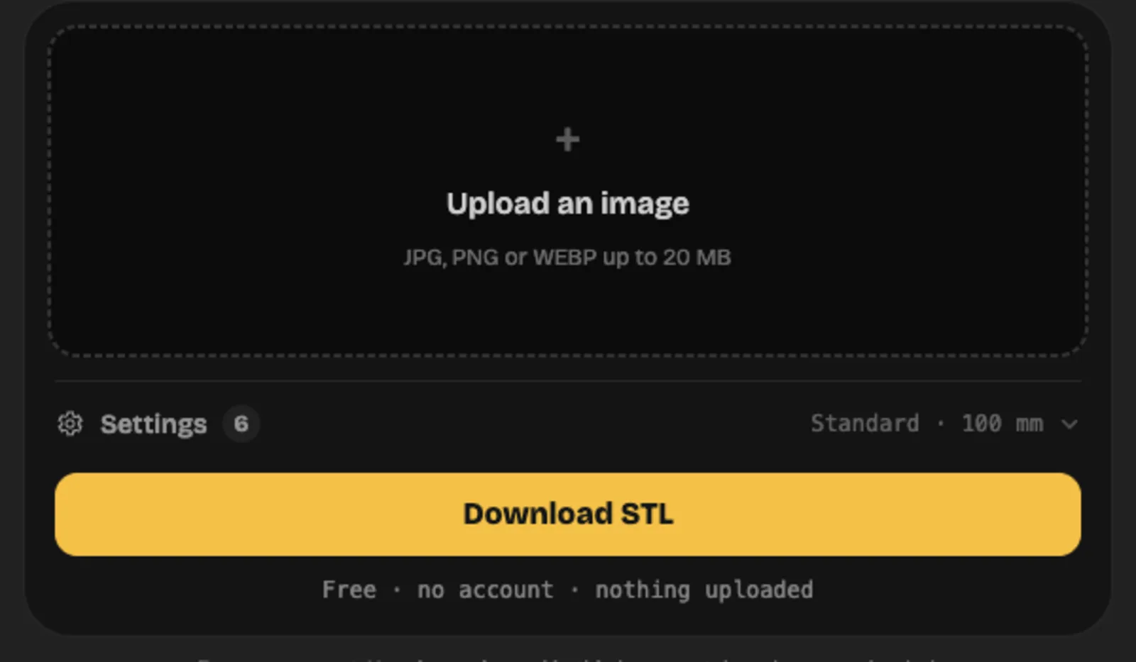
Open the image to STL converter and choose the logo image. It accepts JPG, PNG or WEBP up to 20 MB. The conversion runs in your browser tab, requires no account and uploads nothing. Keep the tab available until you have checked the dimensions and saved the STL you intend to print.
Make sure the loaded image is the print version you prepared. A full colour presentation sheet can contain a tagline, shadow, border and several alternative marks, all of which can affect conversion. Use one logo per image for this first plaque so the mask and final size remain easy to judge.
Select extrude mode and set the threshold
Switch to extrude mode and start with threshold 0.5. Extrude divides the image into two heights: the base and the raised mark. Set invert so the dark logo is raised and the transparent or white background stays at base height. Check the preview after changing either threshold or invert; a large raised rectangle is a sign that the background has been selected.
Look closely at the smallest letter opening and the narrowest gap between two shapes. Move the threshold a little if grey edge pixels make those features too thin or too heavy. If the mask needs a large change to become recognisable, clean the source image first. A threshold cannot distinguish an intentional dark stroke from a dark compression mark beside it.
Set the physical size, extrusion and base
Set width to 100 mm, extrusion height to 3 mm and base thickness to 1.5 mm. The width setting controls the image's longest side, with the other side following its proportions. The extrusion is added above the base, so the raised areas reach 4.5 mm in this example. Check that a tall logo has the intended height as well as the intended width.
A base connects separate letters and keeps small dots attached. At this size, aim for at least 0.8 mm across the narrowest raised line and 1.2 mm or more for walls that need strength. Enlarge the whole design or adjust its print artwork if the smallest features miss those values. Increasing extrusion height only makes a narrow feature taller; it does not make that feature wider.
Check the triangle count and download the STL
Review the dimensions and triangle count before downloading. A 256 to 512 px sampling resolution is a practical starting range for a 100 mm logo. A square 256 px grid produces 133,110 triangles and about 6.7 MB of binary STL; a square 512 px grid produces 528,374 triangles and about 26.4 MB. Use the count shown for your actual image because rectangular proportions change the grid.
Download the closed binary STL and give it a useful name, such as club-logo-100mm-base1.5-raised3.stl. Keep the PNG alongside it. The file describes the solid geometry in millimetre coordinates and does not contain the image's colours. You will choose the filament colour or assign multiple materials in the slicer.
Slice with the flat face down and print a sample
Import the STL into your slicer, confirm the 100 mm dimension and place the flat back on the build plate. Start with the profile for your printer and filament, a 0.4 mm nozzle and 0.2 mm layers. Slice the model and examine the first layer, the base's top surface and the first layer containing the raised logo. Check that every letter has toolpaths and sits on the base.
Print one example or a cropped section containing the smallest lettering at its final scale. Let it cool before removing it, then check readability, edge quality and attachment to the base. Save the slicer project with the successful settings. If you plan a colour change, add it at the layer where only the raised logo continues and confirm that boundary in preview.
Prepare the Logo Image
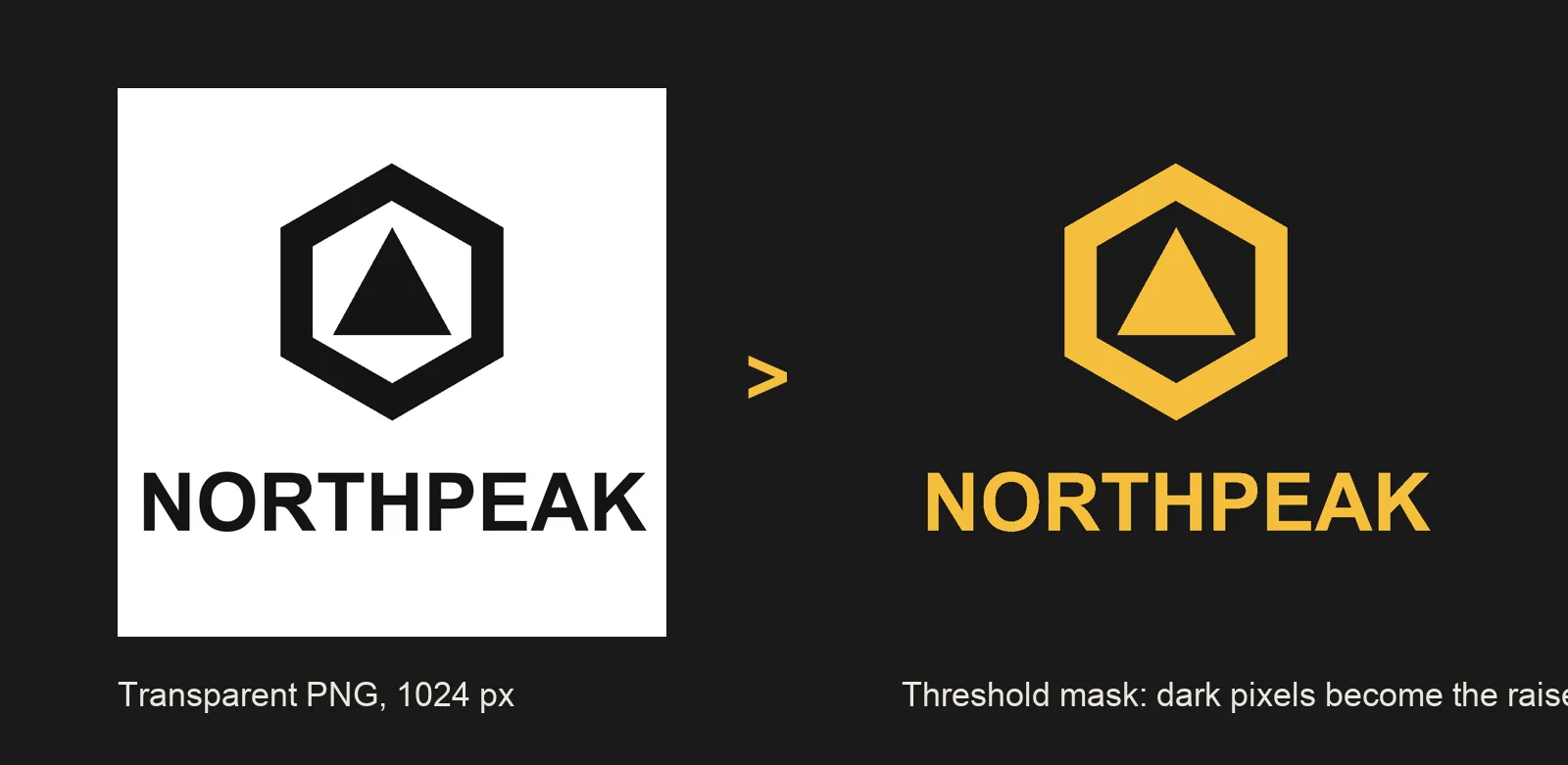
Make a single dark silhouette for an extrusion. Coloured regions with different brightness values can fall on different sides of the threshold, even when they look equally prominent on screen. A yellow shape can disappear while a blue shape survives. Filling all intended raised areas with black gives them the same treatment. Preserve intentional holes inside letters and rings, and keep the spaces between neighbouring shapes open. Remove gradients, soft shadows and glows from this print copy.
Inspect the smallest details in relation to the whole image. If a line is 8 px wide inside a 1000 px wide cropped design, it becomes about 0.8 mm wide when the design is printed at 100 mm. A 3 px line becomes about 0.3 mm and is likely to disappear with a 0.4 mm nozzle. This proportional check helps you choose a useful final size before converting anything. Count the margin as part of the image when doing the calculation, since unused space also consumes the selected width.
Extrude the Logo Into an STL
Extrusion assigns a constant raised height to the selected part of the image. It is useful for flat lettering, outlined emblems and symbols whose identity depends on their silhouette. Relief mode uses brightness to vary height across the surface, which suits tonal images and shallow sculpted effects. Choose extrude when a letter should have a level top and a consistent thickness. A shaded logo processed as relief can create uneven letters that are difficult to colour with a single filament change.
Transparent pixels are treated as white and stay at base height when the dark logo is selected. They do not remove the base under the blank part of the image. The result is a raised logo on a closed backing, with all its separate islands connected through that backing. If you want the outside edge of the physical object to follow the logo itself, use a vector outline and a CAD or slicer workflow that creates that shape. Transparency controls the raised region in this converter.
Slice and Print the Logo
Place the broad, flat back against the build plate. That orientation gives the base continuous support and lets the raised logo grow directly from it. A simple plaque usually needs no supports in this position. Rotate the object only when another requirement justifies it, such as fitting a long sign diagonally on the bed. Standing thin letters upright adds stability problems and can put supports against the faces you want to read.
Pay attention to the transition above the base. A 1.5 mm base does not land neatly on every 0.2 mm layer sequence, especially when the first layer has a different height. Find the actual transition in preview before inserting a filament change. For a later production version, you can choose a base height that aligns with the selected layer schedule. Keep enough solid top surface beneath the logo so the first raised layer is supported across its whole footprint.
Extrude your logo now
Drop a transparent PNG into the converter, set the height and download a closed STL in millimetres. It is free and runs in your browser.
3D Printing Logo Methods: Extrude, Emboss, Full 3D
Choose the method by the physical result you need. A flat sign uses the logo's existing outline. A branded enclosure needs a raised or recessed feature attached to a known surface. A mascot figurine needs volume beyond the visible outline. A precisely mounted badge may need dimensions and holes that are easiest to control in CAD. These are different modeling jobs even when they begin with the same image.
You can combine methods within one project. Extrude the lettering, model a stand with measured slots, and generate a rounded mascot for the centrepiece. Keep each part's purpose clear and check the joins before printing. For a first attempt, choose the route that answers the largest requirement, then add the small mounting or finishing details after the logo itself prints cleanly.
Extrude a flat logo
A free browser converter turns a thresholded raster image into a raised shape on a base with a controlled height.
- Preserves a prepared silhouette and the spacing between its elements
- Needs no account and processes the image in the browser
- Gives you a closed STL with dimensions and triangle count before download
- The output follows image sampling, so a poor source leaves rough contours
- The base remains under transparent areas of the image
- The shape has constant raised height and cannot supply a rounded mascot body
Best for: Signs, plaques, flat badges and an initial test of your logo at print size
Emboss or deboss on an existing model
A CAD tool or compatible slicer joins the logo to a part or subtracts it to form a recess.
- Places the mark directly on the object you already intend to print
- Supports raised lettering, engraving and separate colour regions
- Lets you preserve a useful flat face for mounting or handling
- Requires careful placement and a real overlap with the host model
- A recess reduces the remaining wall thickness
- Curved faces and steep undersides may need additional modeling or support checks
Best for: Enclosures, lids, tool handles, presentation stands and branded accessories
Full 3D model from the picture
Opolyo uses one picture to generate a mesh with sides and a back; Standard textures cost 10 credits.
- Builds volume for mascots and shaded emblems
- Provides a mesh that you can inspect from every side
- Offers a route from a concept image to a printable model after mesh and slicer checks
- Hidden surfaces are inferred and need your review
- Exact lettering and brand proportions can change
- Thin appendages, balance and mounting features may need further work
Best for: Mascot figures, sculptural emblems and display pieces with a substantial body
Model it in CAD
Tinkercad or Fusion 360 can build a dimensioned logo assembly with its base, holes and mechanical connections.
- Gives direct control over thickness, clearances and mounting dimensions
- Keeps repeated dimensions consistent across a set of parts
- Can combine vector profiles with a purpose-built stand or enclosure
- Takes more setup and familiarity with solid modeling
- Complex artwork may need path cleanup before import
- Organic sculpting can require a different modeling workflow
Best for: A badge that must fit a recess, a fitted nameplate or a sign with measured hardware
Our take
Use extrusion for a recognisable flat mark whose front outline is already correct. It gives you a direct first test of size, stroke width and readability. Choose embossing when the logo belongs on an existing part, and check the remaining wall before you subtract a recess. Use CAD when the fitting dimensions are central to the job, such as a plaque that must snap into a holder or align with two screws.
Choose a full model when the artwork contains a character or emblem that benefits from rounded volume. You can print that model on a separate base carrying accurately extruded text. Separating the sculptural and typographic parts gives each a suitable workflow and makes later revisions easier. Whichever route you choose, keep the editable source, exported mesh and slicer project together so the next copy matches the first successful print.
Making a 3D Printer Logo File the Slicer Accepts
A PNG, JPG or SVG describes artwork. A slicer needs a solid volume or an import operation that creates one. Extruding the artwork adds the missing thickness, and exporting STL records that surface as triangles. The slicer then creates perimeters, infill and top surfaces for the selected printer. Keep those stages separate when diagnosing a problem: a missing letter in the mesh calls for an artwork or geometry change, while a missing letter only in the layer preview points toward feature size or slicing settings.
A usable solid has a closed boundary, consistent surface orientation and enough physical thickness to survive printing and removal. The browser converter supplies a closed base and walls, with a minimum permitted base thickness of 0.2 mm. That limit makes a volume possible; a handled plaque usually benefits from a thicker base. If you cut the mesh, combine it with another object or add holes, inspect the result again. An edit can introduce open boundaries even when the original export was sound.
Use STL for the plain single-mesh route. It is widely understood by slicers and carries the outline, base and raised geometry you need. It does not preserve the PNG's colours or store a standard millimetre unit field. After import, measure the longest side and assign the material. Save a slicer project when you want to retain the printer profile, plate layout and colour decisions for a repeat job. A geometry export and a complete print project serve different stages of the work.
Minimum Line Width and Extrude Height
For a typical 0.4 mm FDM nozzle, start with a minimum raised line about 0.8 mm wide, giving room for roughly two extrusion paths. Use walls 1.2 mm or thicker where strength matters. These are practical starting values, and the selected line width and slicer wall generator still affect the result. A small decorative stroke on a supported plaque has an easier job than a long, exposed branch of the same width on a keychain.
Measure at the narrowest part of the design. A serif can taper from a healthy 1.5 mm stem to a point that has no printable width at all. The slicer may shorten that point even when the main letter prints perfectly. Widen vulnerable ends, simplify fine ornaments and open narrow gaps in the print artwork. If exact brand geometry must stay unchanged, increase the finished size until the smallest important feature has room for continuous toolpaths.
Extrusion height controls how far the logo stands above the base. A 2 to 4 mm rise gives a small sign a visible edge, while a shallow embossed mark on a lid can start around 0.6 to 1 mm. Deep, thin letters become more vulnerable to sideways force and take longer to print. Choose enough height for the desired shadow, paint boundary or colour separation, then check whether the surrounding object can protect the raised detail during use.
Computed 2026-09-22 with the converter's own mesh formula for a square logo. The bar is file size in MB. 256 to 512 px is enough for a 100 mm logo; more pixels add triangles, not detail a 0.4 mm nozzle can print.
Transparent PNG vs White Background
A dark logo on a transparent PNG and the same logo on a clean white background can produce the same raised mask. The converter treats transparent pixels as white before building the height grid. With the dark-logo polarity selected, both backgrounds remain at base height. Transparency is useful for keeping unwanted page elements out of the source, but it does not create a hole through the base or automatically trim the backing to the outside of the symbol.
A white background works well when it is truly white and the logo is clearly darker. A JPG can contain pale halos, compression blocks or off-white paper around the mark. Some of those pixels may cross the threshold and become small raised flecks. Zoom into the mask before exporting, particularly around curved edges and thin letters. If a photographed page has uneven lighting, clean the background in an image editor so one threshold can separate the whole logo consistently.
Use invert when the selected raised area is reversed. A light logo on a dark field needs a different polarity from a dark logo on white. Check a known solid region and a known empty region after the change. Moving the threshold will change which intermediate tones enter the mask, so confirm both polarity and edge quality together. A preview full of raised background usually indicates an image-selection problem long before it indicates a printer problem.
Adding a Logo SVG in Bambu Studio
Use the SVG route when you have clean vector artwork and want to place it directly on a model. In Bambu Studio, select the host object and use its SVG import or add-part workflow, then inspect the imported shape in the object list. OrcaSlicer also provides an SVG workflow in compatible versions. Interface labels can vary, so confirm that the imported logo belongs to the intended object and has the intended part type before moving it onto a face.
Set the logo's size, rotation and extrusion depth, then position it on a broad, accessible face. For a small raised mark, a depth around 0.6 to 1 mm is a useful first test. Give the logo a small overlap with the host so its volume connects cleanly. For a recess, use a negative volume and check the remaining wall beneath it. Slice the assembly and inspect the layers at the surface boundary to verify that the addition or subtraction actually happened.
Prepare the SVG as filled paths before importing. A visible stroke is a line with a display width, and an importer may interpret it differently from a closed filled outline. Convert strokes to paths and convert text to outlines in your vector editor, preserving the holes inside letters. Remove clipping effects and embedded bitmap images from the print copy. A file ending in .svg can still contain a raster picture with no usable vector contour, so inspect its paths if the import appears empty.
For a simple plaque that starts as PNG, the browser extrusion workflow avoids a separate tracing stage. Use the SVG route when you already have clean paths or need to add the logo to an existing object. On a curved face, inspect the entire contact area from several angles; surface placement controls can leave uneven depth or partial contact on difficult geometry. Save the assembled slicer project so the logo position and part settings survive the next session.
Embossing or Debossing a Logo Onto an Existing Print
Embossing adds a raised logo to a surface. Debossing cuts the same outline into that surface. Start by choosing a face large enough for the mark and checking what sits behind it. A box lid may have ribs, screw holes or a sealing surface close to the decoration. Leave enough uninterrupted material to preserve those functions. Put the logo on a copy of the model so you can compare the modified part with the original dimensions.
For an embossed mark, extrude the outline and overlap it slightly with the host before joining the solids or assigning it as a positive part. A typical first test is 0.6 to 1 mm above a horizontal face, with strokes at least 0.8 mm wide for a 0.4 mm nozzle. Check the underside of every letter when the face is vertical. Raised details can create unsupported ledges, so orientation and overhangs matter even when the overall object needs no supports.
For a debossed mark, use the extruded shape as a cutting volume. Start with a shallow recess and measure the wall that remains. Cutting 0.6 mm into a 2 mm wall leaves 1.4 mm before any other features are considered. Check that the cut does not enter a nearby cavity, fillet or screw channel. Recessed marks are useful for paint fill and surfaces that should feel smooth during handling, while deep narrow grooves can be difficult to clean or finish.
Inspect the combined result as sliced layers, especially when working with a downloaded mesh. Merely grouping two objects may preserve them as separate overlapping shells. Confirm that the host and raised logo print as a connected volume and that a recessed logo actually removes material. If the face is strongly curved, make a small test section or use CAD to control the cut. A local test reveals shallow spots and unsupported edges before you commit to the entire part.
Emboss vs deboss at a glance
Choose the surface treatment by how the part will be viewed and handled. Raised lettering catches light and creates a clear height boundary for a filament swap. A recess protects the outline from rubbing and can hold paint below the surrounding face. Both methods need enough line width and open space to survive slicing at the final size.
The height and depth values below are starting points for a small FDM mark with a 0.4 mm nozzle. Test the actual face orientation and material. A horizontal top face supports raised lettering directly, while a side face changes the support conditions and the way the layer lines cross the logo.
| Choice | Emboss (raised) | Deboss (recessed) |
|---|---|---|
| Readability | Raised edges catch light; contrasting upper layers make the outline clear | Recessed edges create shadows; paint fill improves small details |
| Minimum height or depth | Start around 0.6 to 1 mm high with strokes at least 0.8 mm wide | Start around 0.4 to 0.8 mm deep and preserve a strong wall beneath the cut |
| Supports | Usually unnecessary on an upward face; check ledges on side faces | Usually unnecessary for shallow upward recesses; inspect any roof on side faces |
| Paint or filament change | Paint the top or change filament above the host surface | Fill the recess with paint or use a separately assigned inlay |
| Best on which faces | Broad top faces and display surfaces with room for raised detail | Handled surfaces and broad faces with sufficient wall thickness |
| Tools | CAD join or positive logo part in a compatible slicer | CAD subtraction or negative logo part in a compatible slicer |
Logo to 3D Model With AI
The image to 3D generator builds a full mesh with a back and sides from one picture. Use it when a mascot, animal emblem or shaded character should become a small sculpture. The picture supplies visible shape cues, and Opolyo infers the surfaces you cannot see. A side view of the result may therefore contain new geometry that needs your approval before printing, especially when the logo has a recognisable pose or accessory.
Prepare one JPG, PNG or WEBP up to 10 MB with the subject clearly separated from its surroundings. A shaded emblem provides more clues about volume than a flat wordmark. Small letters, exact spacing and tightly controlled outlines are better handled through extrusion. You can generate the mascot and place it on a base with separately extruded text, preserving readable typography while giving the character a rounded body. For a logo that exists only as an idea, text to 3D offers another starting point.
Choose triangle topology for a print and begin around 100,000 to 300,000 faces for a modest display model. The available face limit spans 500 to 2,000,000, but extra faces cannot compensate for missing volume or thin supports. Standard textures cost 10 credits. Judge the printable form with its texture hidden when possible, then rotate it through the back, underside and narrow protrusions. Texture shading can suggest a groove or letter that has no corresponding depth in the mesh.
Keep the GLB as the generated source and use the workspace converter for the format your next tool needs. Available conversion outputs include FBX, OBJ, STL, glTF, USDZ and 3MF, with basic conversion at 2 credits and advanced conversion at 3. After export, check physical scale, a stable base and support contact points in the slicer. A complete mesh still needs a print orientation and sufficiently strong details for the chosen material and finished size.
When a 2D Logo to 3D Converter Beats Extrusion
Choose a full model when the object should remain interesting as you walk around it. A club mascot with a head, body and visible limbs benefits from rounded volume. A circular badge seen mostly from the front often works well as a simple extrusion. Imagine the intended side view before choosing the route: a constant-depth edge calls for extrusion, while a shaped profile and a developed back call for reconstruction and review.
Inspect balance and attachment points before committing to scale. A mascot standing on two small feet may need a support base, and an extended tail may be too thin at keychain size. At the intended dimensions, look for weak necks, long isolated projections and deep recesses that collect supports. Thicken, shorten or support those features in an editor as needed, then slice a small test of the weakest area at full scale.
AI 3D Logo Generators Compared
These tools cover different starting points, including a parametric route and a manual SVG workflow. Choose by the input you have and the geometry you need to inspect. For a print, confirm that the output contains actual raised or rounded surfaces wherever the logo needs physical detail. A textured preview alone cannot establish that.
Read the output column as a file path through the workflow. A GLB can hold the generated mesh, while an STL or suitable 3MF takes it into the printing stage. Keep conversion costs separate from generation, and retain the original asset when you may want its colours for a digital preview later.
| Tool | Input | Output for printing | Price basis |
|---|---|---|---|
| Opolyo | One picture | GLB then STL or 3MF | Credits from $19.99 per month |
| Sloyd | Parametric | GLB | Subscription |
| Meshy | Image or text | GLB/OBJ/STL | Credits |
| Blender with the SVG import add-on | SVG | Any format | Free software |
Turn the logo into a full model
Upload one picture, preview the mesh from every side and download STL for the slicer. Standard textures cost 10 credits; plans start at $19.99 per month.
What 3D Printed Logos Look Like: Signs, Keychains, Stamps
Signs and desk plaques are forgiving first projects because the broad base holds every part of the logo together. Add a separate stand, a slot or mounting holes after you establish the right reading size. A desk plaque needs enough support behind it to resist tipping, while a wall sign needs an attachment method that suits its weight and mounting surface. Leave room around fasteners so tightening them does not split the nearest thin stroke.
For a keychain, give the ring a dedicated loop with substantial material around the hole. Join that loop to the base across a broad area and soften the transition with a fillet where your editor allows it. A ring pulled through a thin letter can tear it away. Print the keychain flat, inspect the loop's perimeters and test a sample by hand before making a batch. Keep decorative points short enough to survive pockets and bags.
A rubber stamp needs mirrored artwork on its printing face so the transferred impression reads correctly. Mirror exactly once, and mark the source version clearly to avoid reversing it again in the slicer. Keep raised stamping areas at a common height and leave enough clearance around them to avoid background contact. The appropriate flexible material and finishing depend on the stamp process; a rigid printed prototype is useful for checking layout and pressure before making the final stamp.
Cookie cutters need an outline wall and a comfortable reinforced rim, with any internal impression details designed separately. A filled extrusion does not automatically become a usable cutter. Cake toppers need a supported stem or mounting stick, and coasters need a stable surface that will hold a cup without rocking on tall letters. For food-related use, choose a suitable material and fabrication process for that application. Keep the logo geometry separate from assumptions about what a finished surface can safely contact.
- Turn a logo into a print1,310 searches31%
- See printed logo examples980 searches23%
- Add a logo SVG in Bambu Studio1,600 searches38%
- Logo to 3D model with AI360 searches8%
Monthly US searches, Semrush, read 2026-08-21 and 2026-09-14. The Bambu Studio question appeared in a single recent month, so treat its volume as provisional.
Printing 3D Print Logos in Two Colours
A single filament change works when the base finishes before the raised logo begins. Print the base in one colour, pause at the transition and continue the raised areas in the second colour using your printer's supported change procedure. Find the transition in the layer preview and check that every feature above it should share the new colour. A tall border that continues alongside the letters will change colour too, so include the border height in your design decision.
A multi-material system can assign colours to different parts or regions at the same height. Import or define those regions clearly, check their alignment and preview the material assignments layer by layer. Look at the purge allowance and estimated waste for small badges, where colour changes can consume a noticeable share of the total filament. A design with one height-based change is efficient to batch, while an interlocking multicolour face may require many changes throughout the job.
Separate letters can also fit into recesses in a printed base. Create the base and inserts at matching dimensions and add clearance so they assemble after printing. A starting FDM clearance of about 0.2 to 0.3 mm per side needs a test with your material and printer. Make one representative letter and pocket first, leaving space for any adhesive you intend to use. Save both meshes at the same scale, and label them so later reprints do not mix incompatible versions.
Paint fill suits recessed artwork, and a small roller or careful brush can colour a raised face. Clean and prepare the surface for the paint system you choose, keeping coats thin around narrow counters and channels. Test adhesion on a spare piece of the same filament. With any colour method, inspect the uncoloured print first: broken strokes, weak loops and missing material should be corrected in the design or slicing stage before finishing.
What a 3D Printed Logo Costs to Make
The extrusion route costs nothing on Opolyo. The browser converter needs no account, uploads nothing and adds no watermark to the output. Your physical costs are filament, machine time and any mounting or finishing supplies. Once the file prints correctly, you can reuse it for more copies without repeating the conversion. Keep the successful slicer project so a second batch uses the same dimensions, layer settings and colour boundary.
For a full 3D logo, Standard textures cost 10 credits, with conversion handled as a separate workspace operation when needed. Basic conversion, including 3MF output, costs 2 credits; advanced operations such as quad remeshing cost 3. Plans start at $19.99 per month and a one-time pack is available through pricing. Check the operation you are selecting before spending credits, particularly when the target is a simple flat wordmark that the free extruder already handles.
A 100 mm by 40 mm by 4 mm sign uses roughly 12 to 20 g of filament and can take about 30 to 60 minutes with a 0.4 mm nozzle at 0.2 mm layers. Those are planning estimates: coverage, perimeters, solid layers, infill, speed and colour changes affect the actual total. Use the slicer's estimate for the final geometry and selected printer profile.
Calculate material cost from the estimated grams and the price of your spool. For example, at an assumed $20 per kilogram, 12 to 20 g represents about $0.24 to $0.40 of filament before waste. Add purge material, a failed first sample, adhesive or paint when they apply. For a batch, separate the one-time design work from the per-copy printing work so you can see whether a small simplification will save useful time across the whole order.
Opolyo credit costs, 2026-09-22. Plans start at $19.99 per month; a one-time pack is available.
Start with the free extruder
Most logos need thickness, not a full model. Extrude yours in the browser now, and keep the generator for the mascot.
Fixing Common Logo Print Problems
Locate the first stage where the problem appears. Compare the source image, the converted mesh and the sliced layers at the same intended size. A rough outline already present in the mask needs an artwork or sampling correction. A clean mesh with missing toolpaths needs a feature-width or slicer adjustment. When both previews look correct, inspect the physical print and the selected printer profile.
Change one relevant setting and print a small sample containing the affected feature at full scale. Keep the previous export so you can compare the result. The checks in the table cover the common failures for a flat logo and give you a concrete next action before you repeat the complete job.
For a repeated batch, check the first finished copy before releasing the remaining jobs. Compare its smallest letters, base flatness and mounting holes with the saved project. A material or nozzle change can alter these features even when the source STL stays the same.
| Problem | Cause | Fix |
|---|---|---|
| Rough edges | Low-resolution artwork, compression noise or coarse image sampling leaves a stepped contour | Use the original artwork, clean the mask and compare 256 with 512 px sampling; inspect the STL contour before changing printer settings |
| Thin lines missing | A stroke becomes narrower than the usable extrusion width at the chosen scale | Widen the stroke toward 0.8 mm or enlarge the logo, then confirm continuous paths in layer preview |
| Letters floating | Separate logo elements lack a shared base or sit above the host without overlap | Keep a connecting base or join each element to the host with real overlap; inspect the first layer beneath each letter |
| Background printed too | The mask selects the background, or the expected transparent area is actually the retained base | Correct invert and threshold for a raised-background error; use an outline-based workflow if you need the backing removed outside the logo |
| Mirrored text on a stamp | The printing face was left readable or the artwork was mirrored twice | Mirror the stamp face exactly once so its impression reads normally; test a small impression before finishing |
| Warped corners | The broad base lifts as the material cools or first-layer adhesion is weak | Check bed cleanliness and the material profile, verify the first layer and try a suitable brim before repeating the full plaque |
| Holes in the base | An edited mesh has open boundaries, the base is too thin or the sliced top surface is insufficient | Inspect and repair the source mesh, use a practical 1 to 2 mm base and check solid layers across the backing |
| The model is tiny or huge in the slicer | The importing program interpreted unitless STL coordinates at the wrong scale | Set the known longest dimension in millimetres, confirm total height and save the corrected project before printing |
3D Print Logo FAQ
Convert a clean logo image into a solid with a base and a raised outline, then export STL. For a first FDM print, try a 100 mm longest side, a 3 mm extrusion above a 1.5 mm base and strokes at least 0.8 mm wide. Slice with the flat back down and check that every letter has toolpaths before printing.
Prepare a dark logo on a transparent or white background and use extrude mode in an image to STL converter. Set the threshold, physical size, raised height and base thickness, then download the closed mesh. Import it into your slicer and verify the dimensions and layer preview.
PNG, JPG or SVG can serve as the source artwork, but the printer workflow needs geometry with thickness. STL is a common mesh format for the slicer, and a compatible 3MF project can retain additional print information. The slicer then produces the machine file for your printer.
Prepare the SVG as filled paths with outlined text, select the host object and use the SVG import or add-part workflow. Set the size, depth and face placement, then choose a positive part for embossing or a negative part for a recess. Inspect the sliced layers to confirm contact and the intended effect.
For a small plaque, start with a 1 to 2 mm base and a logo raised 2 to 4 mm above it. With a typical 0.4 mm nozzle, keep raised lines about 0.8 mm wide or more and structural walls at least 1.2 mm thick. Test exposed details and mounting points for the way the finished object will be handled.
Extrude the logo outline, place it on the model and give it a small overlap with the host surface. Join the solids in CAD or use a positive part in a compatible slicer. Start with a shallow rise around 0.6 to 1 mm and inspect the layer preview for continuous attachment.
Yes, a raised logo can use a filament change where the base ends and the lettering begins. A multi-material system can assign colours to separate regions at the same height. Separate inserts or paint fill also work when the design includes suitable recesses and clearances.
Extrude a flat silhouette when you need its existing outline with thickness. For a rounded mascot or shaded emblem, generate a full mesh from the picture and inspect its back and sides. Check scale, thin features and supports before exporting or slicing for the final print.
Yes, Opolyo can generate a full mesh from one JPG, PNG or WEBP up to 10 MB. Mascots and shaded emblems provide useful volume cues, while exact flat lettering is better suited to extrusion. Review inferred surfaces and confirm that important details exist in the geometry before printing.
Export the source at 1024 px or more on its longest side when the original artwork supports that detail. For a 100 mm logo, 256 to 512 px mesh sampling is a practical starting range. A larger sampling grid adds triangles and file size, so compare the actual contour before increasing it.
Rough contours can come from a small source image, compression noise, a poor threshold or coarse sampling. Inspect the mesh outline and sliced paths to see whether the roughness exists before printing. If those are clean, check printing conditions such as extrusion, cooling and the chosen material profile.
A single-piece logo must fit your printer's usable build area with room for any brim or supports. Larger signs can be split into sections with planned joins and mounting points. Recheck base stiffness, attachment and line width whenever you change the size.
The browser extruder is free, while a full 3D generation with Standard textures costs 10 credits. Basic workspace conversion costs 2 credits and advanced conversion costs 3 credits. Plans start at $19.99 per month, a one-time pack is available, and filament and printer time are separate costs.
Check that you have permission or an applicable licence for the intended use. Access to an image or a generation tool does not grant rights to someone else's logo. For merchandise or public business use, confirm the allowed use with the rights holder before producing copies.
Sources and References
- Bambu Lab Wiki, Import SVG in Bambu Studio (accessed 2026-09-22)
- STL (file format), Wikipedia (accessed 2026-09-22)
- W3C, Scalable Vector Graphics (SVG) 2 (accessed 2026-09-22)
- Blender Manual, Import SVG (accessed 2026-09-22)
Keep going with the logo
Opolyo user
Jaxon uses Opolyo for his own models and writes about what he runs, on the same plans and the same credits as everyone else.
Print your logo this week
Extrude it in the browser or generate a full model from one picture, then download STL for the slicer.