
How to Design Your Own 3D Prints: 4 Ways That Work
Start with what you have, choose a modeling route, then make the result ready for layers, supports and a real print.
You have a printer and an idea, but no model to put in the slicer. You can design your own 3d prints by modeling from measurements, turning a picture into a mesh, capturing a physical object or remixing an existing file.
Those four routes suit different starting points. A functional bracket needs dimensions and fit. A creature in one picture may be quicker to reconstruct. A real part calls for a scan, while a downloaded STL often only needs a cut, a hole or a name added.
The rules for a printable model stay the same whichever route you choose. Finish with an export and slicer check to catch scale, walls, gaps and supports before a long job.
What Designing Your Own 3D Prints Involves
Designing a print means producing a closed mesh that a slicer can cut into layers. The surface needs a clear inside and outside, connected faces and enough thickness for the process you will use.
The work has four stages: idea, model, export file and sliced job. The idea defines the use. The model describes the shape. The export preserves the geometry in a format the next program reads. The sliced job turns that geometry into printer movements.
Beginners often stall by learning full CAD before deciding what they want to print. Start with a small object and a visible success condition. Designing includes generating and remixing, so drawing every vertex from scratch is only one valid route.
The four methods are not equally popular in search. Most people start with nothing and want to design from scratch; a large share already has a file and wants to change it.
- Design from scratch3,700 searches49%
- Edit an existing STL2,610 searches35%
- From a photo or picture790 searches10%
- From a real object430 searches6%
Monthly US searches, Semrush, 2026-08-21 and 2026-09-14. Groups: how to design your own 3d prints and how to design 3d prints; stl editor, online stl editor and 3d print customizer; how to make a 3d model from a picture, how to 3d print a picture and photo to 3d print; how to make a 3d model from an object and how to scan an object for 3d printing.
From Idea to Print File in Four Stages
At the idea stage, write down the job and the constraints. Record the target size, the load it carries, the surfaces that must fit and whether the object should be decorative, flexible or replaceable.
At the model stage, build the volume and test the important dimensions. At export, set millimetres and choose a format. In the sliced job, inspect every layer, then make a small test before committing to the full object.
Which Method Fits What You Already Have
Your starting point is a useful filter. If you have only an idea, a basic CAD tool gives you control. If you have one picture, choose a full reconstruction or a flat relief. If you have the object, capture its dimensions. If you have a file, edit the parts that need to change.
Choose the least complicated route that preserves the detail you need. Every extra stage adds a new place for scale, topology or licence problems to enter the job.
The four methods at a glance
| Starting point | Method | Typical tools | Learning curve | Best for |
|---|---|---|---|---|
| Nothing but an idea | Model from scratch | Tinkercad, Fusion 360, Blender, FreeCAD | Low to high | Functional parts and original shapes |
| A photo or drawing | AI reconstruction or relief | Opolyo, Blender, relief converter | Low | Figures, props, plaques and logos |
| A physical object | Scan and clean the mesh | Polycam, KIRI Engine, Meshmixer | Medium | Copies and replacement parts |
| An existing STL | Remix or edit the file | Tinkercad, Blender, an STL editor | Low to medium | Personalised versions of existing designs |
Method 1: 3D Modeling for 3D Printing From Scratch
Model from scratch when the object must fit another object, follow exact measurements or carry a known load. A replacement cap, spacer, enclosure or bracket benefits from dimensions that you control directly.
Solid CAD treats the design as volumes and operations. Mesh sculpting treats it as a surface made from points and faces. CAD is easier to revise by dimension. Sculpting is faster for organic forms, characters and soft transitions.
Start with measurements, block out the large forms, then refine the details. Add fillets where sharp corners need strength or comfort. Save a version before each major change so a small experiment cannot erase the usable shape.
Picking 3D Modeling Software for 3D Printing
Pick software by the shape you need. A stack of boxes and cylinders is easy in a simple browser tool. A part with a hole pattern needs parametric dimensions. A creature needs sculpting and manual mesh checks.
You can change tools later, so keep the first project small. Learn how to set units, measure an object, make a solid, inspect the surface and export an STL. Those skills transfer between programs.
Tinkercad, Fusion 360, Blender and FreeCAD compared
All four can lead to a printable model. Their strengths differ by shape, dimension control and how much mesh cleanup you want to do.
Tinkercad
A browser tool built around simple shapes.
- Minutes to learn
- Fast for boxes, holes and combinations
- Easy to share a small design
- Weak for organic forms
- Limited precise fillets
- Less control over complex surfaces
Best for: First projects and simple household parts
Fusion 360
Parametric CAD for dimensioned designs.
- Strong for mechanical parts
- Dimensions remain easy to revise
- Hobby licence exists
- Heavier to learn
- More setup than a shape editor
- Organic sculpting is not its main strength
Best for: Parts that fit, move or repeat
Blender
Open source mesh modeling and sculpting software.
- Best for organic shapes
- Powerful sculpting and modifiers
- Large ecosystem of modeling tools
- Manual work is needed to keep meshes watertight
- Dimensions take more attention
- The interface has many unrelated tools
Best for: Figures, artistic models and mesh edits
FreeCAD
Open source parametric CAD.
- Capable dimensioned modeling
- Good for revisable solids
- Useful for technical parts
- Interface takes longer to learn
- Organic work is less direct
- Some workflows need careful feature order
Best for: Open source mechanical modeling
Our take
Pick by the shape you need and the dimensions you must control. Pick the one whose workflow you can finish and inspect on a small project.
CAD or Mesh: What a 3D Printer Modeling Program Changes
CAD solids are watertight by construction when the feature history creates a valid volume. You sketch a profile, extrude it, cut a hole or join another body. The program keeps track of the boundary as the design changes.
A sculpted mesh needs a separate check. It may contain a hole, an internal face, flipped normals or two shells that only appear joined. Before export, inspect the mesh and close problems. A slicer can sometimes repair them, but a clean source is easier to revise.
How to Make 3D Models in Blender Without Getting Lost
Set the scene units to millimetres and keep the object scale applied. Block the design with cubes, cylinders and spheres. Use a boolean modifier for clean cuts, and use Solidify when a surface needs a controlled wall.
Run the 3D Print Toolbox add-on check before export. Look for non-manifold edges, thin areas and intersecting geometry. Export STL after the object has the right size, then open it in the slicer and inspect the layers.
Method 2: How to Make a 3D Model From a Picture
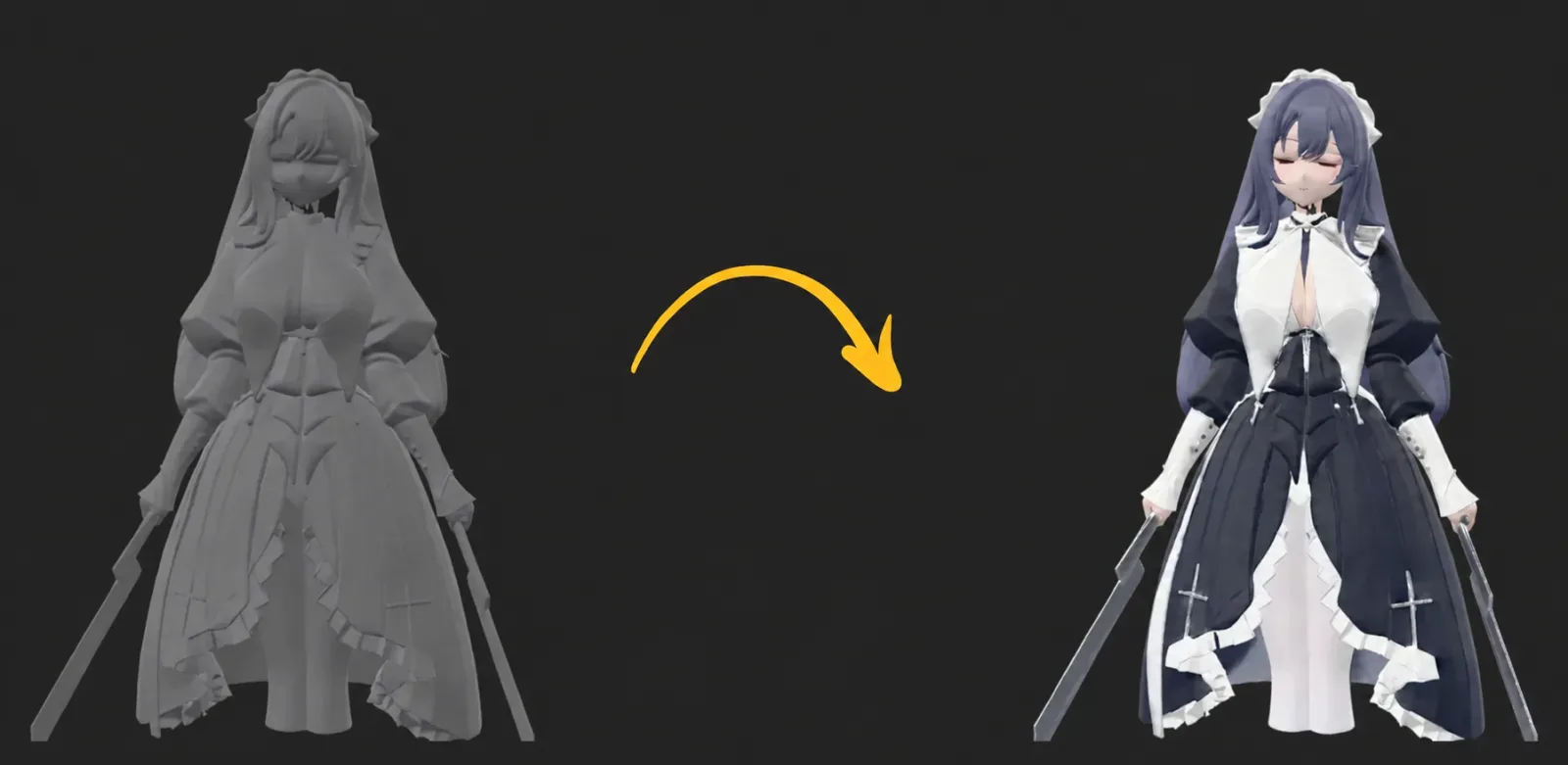
A picture can become a full object or a relief. A full object has a back and sides that are inferred from the visible view. A relief turns brightness or edges into height on a flat plate.
Use a clear photo, drawing or screenshot for a full reconstruction when you want a figure, prop or organic object. Use a logo, portrait or high-contrast design for a relief when the flat back and controlled outline matter.
One clearly visible object on a clean background works best for the full route. Drawings and screenshots work too. Flat line art carries less depth evidence, so the resulting thickness and hidden surfaces need a closer check.
AI 3D Print Generator: One Photo to a Full Mesh
A single-image generator such as the Opolyo image to 3D generator builds a complete mesh from one visible subject. The output has a real back and sides, so it can enter a slicer after review. The back is inferred from the one visible view, which makes the preview important.
Upload one JPG, PNG or WEBP up to 10 MB. One object on a clean background gives the clearest boundary. Choose triangle topology for a print, keep a practical face budget, and inspect thin protrusions before you commit to a large job.
From one picture to a printable STL
This route takes one clear picture through generation, inspection and slicing. Keep the original GLB if you may need the textured version later.
Pick one clear picture
Choose one subject on a plain background. Use a three-quarter view when the sides matter, and keep the whole outline in frame.
Upload it to the image to 3D generator
Upload one JPG, PNG or WEBP file up to 10 MB. Drawings and screenshots are accepted, and a clean background helps the subject separate from its surroundings.
Choose texture tier, topology and face budget
Choose Standard, Ultra or Max texture quality, triangle or quad topology, and a face budget from 500 to 2,000,000. Use triangle for printing, with around 100,000 to 500,000 faces as a common starting point for a desktop print.
Generate and preview the whole mesh
Turn the model through a full rotation. Look at the base, back, thin parts and surface gaps, because the back was inferred from the visible image.
Download STL for the slicer
Download STL for the print path, or keep GLB when you want colour and textures for another use. OBJ is also available as a browser-side export of a triangle GLB.
Check it in the slicer before printing
Set the scale, orient the model and inspect the layer preview. Watch for thin protrusions, missing faces, floating islands and supports that touch the bed poorly.
Photo to 3D Print as a Relief or Lithophane
A relief is a shallow form raised from a flat back. It works well for portraits, logos, plaques, wall art and lithophanes. It does not need to invent a complete object, so its outline and backing are easier to control.
The relief converter on the Image to STL page runs inside the browser at no charge. It needs no account, no upload and no watermark, accepts JPG, PNG and WEBP up to 20 MB, and turns brightness into height.
It always writes a closed solid in millimetres and shows triangle count and dimensions before download. A transparent-background PNG extrudes the logo alone. Lithophanes need a backlight and a thin plate, while a figurine needs the full mesh route.
AI Generated 3D Models for Printing: Cost and Files
A generation with Standard textures costs 10 credits. Ultra or Max textures and quad topology cost more. The polygon budget does not change the price, and the exact figure shows on the button before you generate. A failed generation refunds its credits. Credits come from a plan or a credit pack.
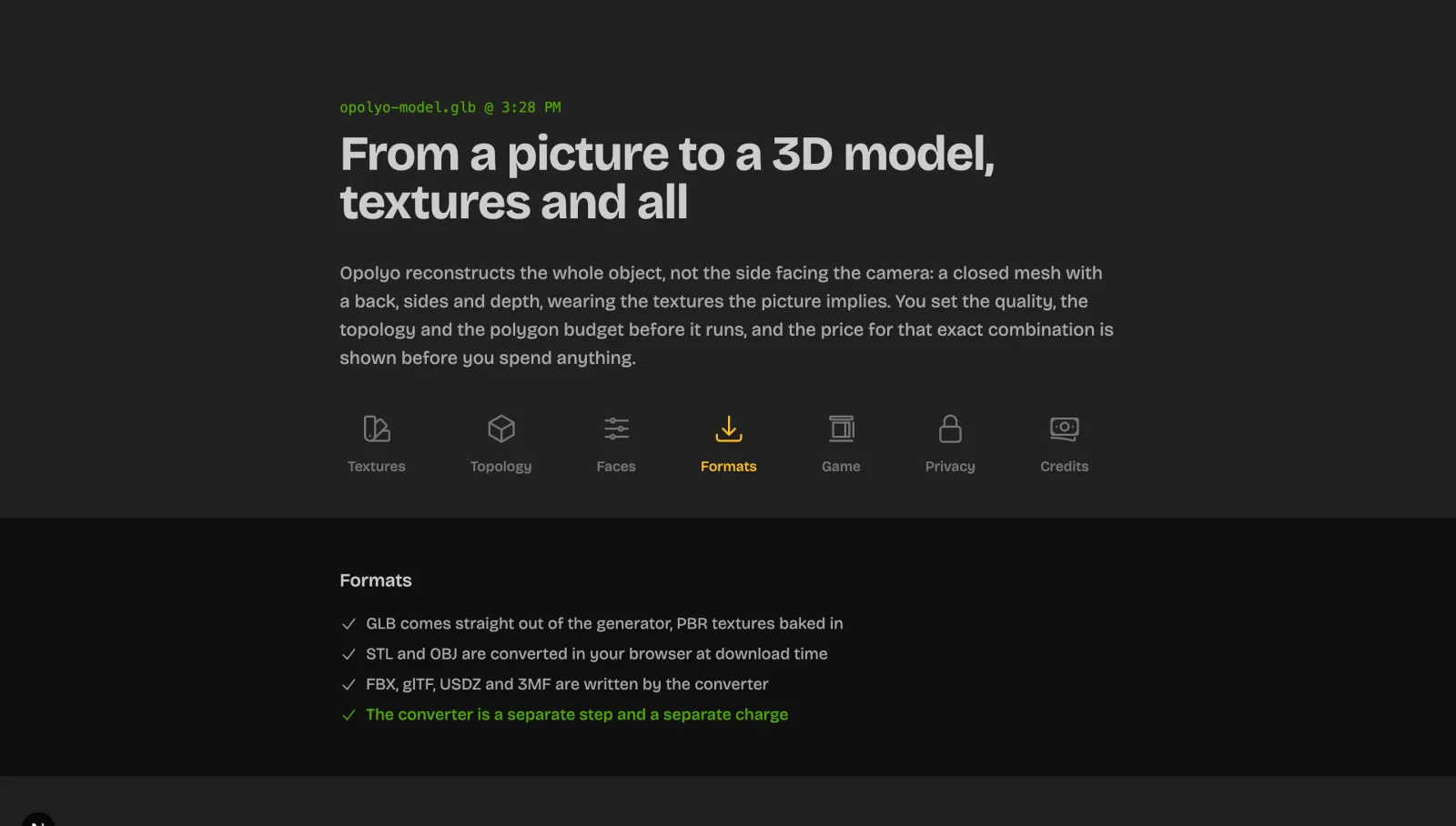
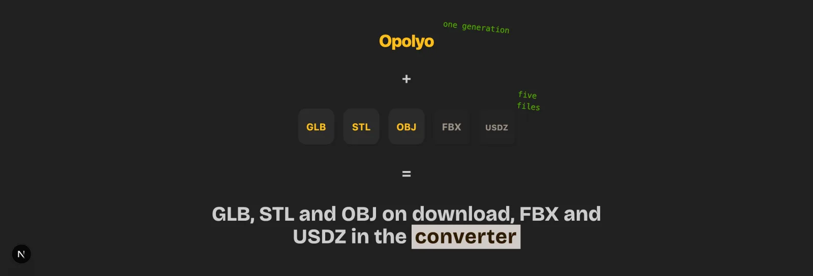
Triangle topology returns GLB. Quad topology returns FBX. STL and OBJ downloads are browser-side exports of the triangle GLB, and STL carries no colour from any tool. Generated meshes come out closed and can be downloaded as STL directly for the slicer.
Generation is usually under three minutes. Preview the slicer before a long print, with thin protrusions and very fine detail at the top of your inspection list. Every paid plan includes a commercial licence for models you generate.
Try it on your own photo
Upload one picture, preview the full mesh and download STL for the slicer. Standard textures cost 10 credits.
Method 3: How to Make a 3D Model From an Object
Scanning captures the dimensions and surface of a thing you can hold. It is useful when the object already exists and you need a copy, replacement part or custom fitting piece. The capture is tied to that physical example.
Photogrammetry uses many overlapping photographs to estimate the shape. Phone apps may use LiDAR when the device supports it. Both routes need a capture session around the object, followed by cleanup and a scale check.
Scans do well with matte, medium-sized objects that have visible texture. Shiny surfaces reflect the room, thin pieces disappear against the background, and small objects may not provide enough detail. Plan the capture around the weakest feature.
iPhone 3D Scanner Apps and Photogrammetry
Polycam and KIRI Engine are common names for phone-based capture. Walk around the object slowly, keep overlap between views and avoid changing the light during the session. LiDAR can help with overall dimensions on supported phones.
The output is a mesh, and it may contain holes, noise or a rough underside. Clean it in Meshmixer or Blender, close the shell and apply a known dimension before export. Treat the scan as raw geometry that still needs the same print checks as any other mesh.
When a 3D Scanner App for 3D Printing Beats a Photo
Choose a scanner when the exact size of a real object matters. The capture gives you observed dimensions and surface details that a single picture cannot measure. It also requires access to the object and time for cleanup.
Choose the picture route when you want a new object or only have one image. You can combine the methods by scanning for reference dimensions and remodeling the final part in CAD. That keeps the measured fit separate from the rough surface capture.
Method 4: Start From an Existing File With an STL Editor
Many first prints are remixes. Start with a downloaded model when the base shape already exists and you only need a different scale, hole, label, cut or connection. This route can turn a useful file into an object that fits your own situation.
Files come from libraries, designers, school projects and your own earlier exports. Check the licence before you change or sell a remix. A permission to print does not always include commercial use, redistribution or derivatives.
An STL editor can move, scale, cut, merge and add text. It cannot easily reshape every surface or restore design history that was lost during STL export. Use a parametric source or remodel in CAD when the change is structural.
Thingiverse, Printables and MakerWorld
Thingiverse, Printables and MakerWorld each contain ready-made designs with different communities and file mixes. Search by the object and the function, then read the photos, comments and recommended print settings before downloading.
Check the licence on every listing. Creative Commons variants can allow sharing, require attribution, limit use to non-commercial work or prohibit derivatives. Download STL for a simple mesh or 3MF when the author includes several objects and print information.
Editing an STL Online or in Blender
A browser editor is enough for simple edits such as scale, a cut, a hole or a label. Tinkercad can import an STL and combine it with simple shapes. Keep the edit small and inspect the result after every boolean operation.
Use Blender for heavier mesh edits, sculpting and repairs. A cut should leave a closed boundary, and a merged object should not contain hidden shells or internal faces. Open the result in a slicer to confirm that the intended volume remains.
3D Print Customizers and Parametric Files
An OpenSCAD customizer, a Thingiverse customizer or a Printables parametric model exposes a few useful numbers. You might enter a name, diameter, length or number of slots and receive a new STL.
This is often the fastest path to a personalised print because the designer already built the relationships between dimensions. Change one value at a time, verify the preview and keep the generated source with the final STL.
How to Design for 3D Printing: Rules That Make It Printable
These rules apply to all four methods. A beautiful generated mesh and a carefully dimensioned CAD part still meet the same layer-by-layer limits once they reach the printer.
Gravity, nozzle width, resin exposure and layer height set practical boundaries. The values below are typical starting points, not universal laws. Test the material and printer you will use for the final part.
Think about orientation while you design. The same shape may print cleanly on one face and need many supports on another. Add flat areas, chamfers, split lines and clearances where they make the job easier.
Typical starting values for a 0.4 mm FDM nozzle and a desktop resin printer; clearance is per side between mating parts. Confirm on your own printer with a tolerance test.
Design rules and typical starting values
| Rule | FDM (0.4 mm nozzle) | Resin | Why it matters |
|---|---|---|---|
| Minimum wall thickness | 1.2 mm (three perimeters) | 0.8 to 1 mm | Walls thinner than this vanish or crack |
| Minimum feature or pin | 1 mm or more | 0.5 mm or more | Small features break off or do not form |
| Overhang angle | Up to 45 degrees without supports | Similar, supports are lighter | Steeper faces sag |
| Bridge length | About 10 mm before it droops | Not a concern in the same way | Long unsupported spans fail |
| Clearance between mating parts | 0.2 to 0.3 mm per side | 0.1 to 0.15 mm | Parts fuse or jam |
| Embossed or engraved text | 0.5 mm deep, 1 mm stroke | 0.3 mm deep, 0.5 mm stroke | Text below this is unreadable |
Wall Thickness and Minimum Feature Size
For FDM, 1.2 mm is a common starting point for a wall with three perimeters using a 0.4 mm nozzle. Resin can reproduce finer walls, but 0.8 to 1 mm is a useful starting range for parts that need to survive handling.
Pins, hooks and letters need enough width to form and enough strength to survive removal. Use 1 mm or more for a typical FDM feature and 0.5 mm or more for resin, then enlarge it when the feature is long, unsupported or exposed to force.
Overhangs, the 45 Degree Rule and Supports
A typical FDM overhang can reach about 45 degrees without supports, depending on cooling, layer height and material. A steeper face leaves each new layer farther over the one below, so the edge can sag.
Replace a sharp underside with a chamfer, split the model into parts, or rotate the feature toward the build plate. Tree supports can reach complex areas with less contact, but they still leave marks and add cleanup.
3D Printing Tolerances for Parts That Fit
Clearance is the space you design between two parts. Tolerance is the amount the real print may vary from the intended dimension. You need both when a peg must enter a hole or two panels must slide together.
A clearance of 0.2 to 0.3 mm per side is a common FDM starting point. Resin often starts around 0.1 to 0.15 mm per side. Print a tolerance test once per printer and material, because holes often print smaller and outside dimensions can grow.
How to Make 3D Prints Watertight
Watertight, or manifold, means the surface encloses a volume with consistent edges and no open boundary. A valid solid has a clear inside and outside. Intersections, flipped normals and duplicate faces can make that logic ambiguous.
CAD solids usually export as closed volumes. For a mesh, run a manifold check, fill holes, recalculate normals and remove internal faces. The slicer needs this information to decide walls, infill and the order of layers.
How to Create 3D Printer Files From Your Design
The design file becomes a printer file through export and slicing. Export creates a mesh file such as STL or 3MF. The slicer turns that mesh into layers, travel moves, temperatures and supports for one printer profile.
Set units before export and confirm a known dimension after import. Then preview the layers. The solid viewport shows the model; the layer preview shows what the printer will actually attempt to build.
Export, check, print
Set units to millimetres before export
Set the modeling scene and object scale to millimetres. Measure one known edge so the exported numbers have a clear meaning.
Export STL or 3MF
Use binary STL for a simple mesh. Use 3MF when you want colour, units and several parts in one file, provided your slicer supports the workflow.
Open in the slicer and look at the preview layer by layer
Import the file, set the printer and material profile, choose an orientation and move through the layer preview. Check the first layer, thin walls, bridges and top surfaces.
Fix what the preview shows
Repair thin walls, floating pieces and missing faces in the model. Adjust orientation, supports or scale in the slicer when the geometry itself is sound.
Save the sliced file and print a small test first
Save the sliced job with its profile and print a small version. Use that test to confirm fit, surface quality and strength before printing the final size.
STL, 3MF and OBJ: Which 3D Printer File to Make
STL is the default because nearly every slicer reads its triangles. It has no units and no standard colour, so millimetres are the usual convention and colour comes from the printer material.
3MF can carry mesh, units, colour, multiple objects and print settings. OBJ can carry a mesh and optional material references. GLB keeps a mesh and textures in one binary file, then needs conversion to STL for the usual print path; the GLB to STL converter does that in the browser.
Print file formats compared
| Format | Carries | Units | Use it when |
|---|---|---|---|
| STL | Triangles only | No units, millimetres by convention | The default every slicer reads |
| 3MF | Mesh plus units, colour, multiple objects and print settings | Stored in the file | Your slicer supports modern project data |
| OBJ | Mesh plus optional material file | Varies by exporter | The model came from a tool that expects OBJ, then convert it to STL |
| GLB | Mesh plus textures in one binary | Scene metadata varies | An AI generator hands you a textured asset, then convert it to STL |
Already have a GLB or OBJ?
Convert it to STL in the browser. No account, no upload, the file never leaves your machine.
Checking the File in a 3D Print Slicer
Use preview mode after slicing and move through the layers. Colours can show speed, material, line type, supports or height depending on the selected view. Read the legend before you act on a colour.
Look for gaps, floating islands, missing walls and abrupt changes. Count perimeters around thin areas and compare the model to a known dimension. A scale sanity check catches metre and inch imports before the bed heats.
STL Repair When the File Will Not Slice
Common errors include non-manifold edges, flipped normals and self-intersections. A slicer may highlight them, omit a region or create unexpected infill. Repair the source when the same file will be exported again.
Start with the slicer's built-in repair. Blender's 3D Print Toolbox and Meshmixer can find and close many mesh problems. Remodel instead when a repair changes the intended surface or creates a shell with unclear thickness.
Common Problems When You Design 3D Print Models
A failed print usually points to one stage that needs attention. Parts can miss their fit because of clearance, walls can disappear because of nozzle width, and a model can arrive at the wrong size because STL has no units.
Use the symptom to choose the next check. Read the model at its original scale, inspect the sliced layers and test the smallest important feature. A short test print costs less time than discovering the issue after a full build.
Symptom, likely cause and fix
| Symptom | Likely cause | Fix |
|---|---|---|
| Parts do not fit | Clearance is too small, holes printed smaller | Add clearance and print a tolerance test |
| Walls missing in preview | Wall is below nozzle or line width | Thicken the wall or change orientation |
| Surface rough or stepped | Shallow slope, low resolution or poor orientation | Rotate the model, raise useful mesh resolution or sand it |
| Model printed at the wrong size | Units were lost or scale was not applied | Check a known dimension in the slicer |
| Model splits or has holes in the slicer | Non-manifold edges, normals or self-intersections | Repair the mesh and inspect the layers again |
| Thin parts snap off | Feature is too narrow or unsupported | Make it thicker, add a fillet or change orientation |
Parts Do Not Fit: Run a 3D Print Tolerance Test
Start with the actual material and printer profile. Print a small strip with several hole and peg clearances, then record which pair slides, presses or binds. Use those observations in the final design.
Keep clearance on the surfaces that move or separate. A press fit needs less space than a sliding fit, and a large part may need more room because shrinkage and heat affect its dimensions. Test again when the material changes.
How to Make 3D Prints Smooth
Smoothness starts in the design. Orient broad visible faces away from steep stair steps, avoid shallow slopes on top faces and use enough mesh resolution for curves. A coarse mesh leaves facets that sanding cannot always remove cleanly.
After printing, sanding and filler primer can reduce visible lines. Resin can provide a smooth finish after the correct wash and cure process. Keep detail that must remain sharp away from aggressive post-processing.
It Printed the Wrong Size
STL has no units. An exporter may write coordinates that represent metres or inches, while the slicer reads the same numbers as millimetres. The mesh can be geometrically correct and still print at the wrong physical size.
Measure one known dimension in the slicer before printing. If it is wrong, scale the model deliberately and apply the scale in the modeling program before another export. Save the corrected file with its unit convention in the name.
Start with the method that fits what you have
A picture is the fastest start. One clear photo becomes a closed mesh in about three minutes, ready for the slicer.
How to Design Your Own 3D Prints FAQ
Start with the method that matches what you have. Use Tinkercad for a simple idea, a single-image generator for a picture, a scan for a physical object or an editor for an existing STL. Then check walls, scale and the slicer preview.
Create or obtain a closed mesh, set its dimensions and export it as STL or 3MF. Open the file in a slicer, orient it, add supports when needed and inspect the layers before printing.
The printing cost depends on material, size, infill, supports and machine time. If you use Opolyo, a Standard texture generation costs 10 credits, while Ultra or Max textures and quad topology cost more.
Use Tinkercad for simple shapes, Fusion 360 or FreeCAD for dimensioned parts, and Blender for organic mesh work. You also need a slicer such as Cura, PrusaSlicer, Bambu Studio or OrcaSlicer to prepare the printer job.
For a full object, upload one clear JPG, PNG or WEBP to an image to 3D generator and download STL after checking the mesh. For wall art, logos and lithophanes, use a relief converter that turns brightness into height on a flat back.
Capture the object with a scanner app or photogrammetry workflow, then clean the mesh in Blender or Meshmixer. Close holes, set a known dimension and inspect the slicer preview before printing.
Choose an orientation that reduces visible steps, use enough mesh resolution and avoid shallow slopes on important top faces. Sanding, filler primer and resin finishing can improve the printed surface after the design is sound.
Export your closed model as binary STL for a basic slicer workflow or 3MF when you need units, colour, several objects and print settings. Open it in the slicer, set the scale and inspect the layers.
Set Blender units to millimetres, block the form with primitives, use booleans for cuts and Solidify for thickness. Check the mesh with the 3D Print Toolbox, close non-manifold edges and export STL.
Yes. You can use Tinkercad, Blender and FreeCAD, or the browser relief converter. The AI route costs credits, with 10 credits for Standard textures.
ChatGPT can write OpenSCAD or Python code that a modeling tool turns into a mesh. It does not output a mesh itself, while dedicated image to 3D generators do create a mesh from an image.
Yes, AI can produce closed meshes that print after normal checks. Inspect thin parts and the inferred back. It suits figures, props and organic shapes, while parts with exact fits should be modeled or measured carefully.
Your own designs are yours, subject to the laws and agreements that apply to your work. Remixes follow the original licence. Models generated on Opolyo paid plans carry a commercial licence.
A common FDM starting point is 0.2 to 0.3 mm of clearance per side, and resin often starts at 0.1 to 0.15 mm per side. Print a tolerance test for each printer and material because holes often print smaller.
Make the surface manifold with no open edges, flipped normals, internal faces or self-intersections. Use a CAD solid when possible, or repair the mesh with the slicer, Blender 3D Print Toolbox or Meshmixer, then confirm the layers.
Sources and References
- STL (file format), Wikipedia (accessed 2026-09-14)
- 3MF Consortium, 3MF specification (accessed 2026-09-14)
- Blender Manual, 3D Print Toolbox add-on (accessed 2026-09-14)
- Khronos Group, glTF overview (accessed 2026-09-14)
- Photogrammetry, Wikipedia (accessed 2026-09-14)
Keep going with the model
Opolyo user
Jaxon uses Opolyo for his own models and writes about what he runs, on the same plans and the same credits as everyone else.
Design your next print from one picture
Upload one photo, preview the full mesh and download STL for the slicer.