
3MF vs STL: Which 3D Printing File Format to Use
Both files describe the same triangles. One of them can also remember your units, colours and print settings.
Your slicer saves a .3mf project, while a download site hands you an STL and an AI generator may give you a GLB. The fork is simple: choose STL to move a bare mesh into almost any printing workflow, or choose 3MF to keep the mesh together with units and supported project information. A 3D model converter can change the container when the next application needs a different format. The useful question is which information you need to arrive with the shape.
For a single plastic bracket, both formats can describe exactly the same surface and produce the same layers. For a plate containing a figure, a separate base and several material assignments, the differences become practical. STL cannot explain which material belongs to each part, what its coordinate numbers mean in physical units, or which support settings you saved. A suitable 3MF project can carry those details, although another slicer may understand only some of them.
Start with the destination: a public model download, a saved project for your own printer, or a file for someone else to edit. Then decide whether geometry alone is sufficient. Keep the original asset, check a known dimension after every conversion, and inspect the sliced layers before printing. The file extension tells you what a container can hold; the exporter, importer and printer determine how much of that information becomes useful.
What Is a 3MF File?
A 3MF file is a package for a three-dimensional manufacturing model. Its name stands for 3D Manufacturing Format. Inside the package, a model can define vertices, triangular faces, physical units, named objects and their placement. Additional resources can describe appearance or information used by a particular application. A .3mf file can therefore represent a simple unpainted part or a much richer printing project, with the same extension on both.
Think of a small enclosure with a body and a lid. A 3MF can keep them as separate objects, position them on a build plate and state that the coordinates use millimetres. When you reopen a compatible project, you can select the lid independently and see its relationship to the body. A generic export may preserve the two meshes and their dimensions while leaving printer-specific choices out. Knowing which kind of export you received helps you judge what should be present.
The format was introduced in 2015 and is maintained by the 3MF Consortium under the Linux Foundation umbrella. Its core specification defines a shared way to describe manufacturing geometry, with extensions for additional capabilities. That common structure makes the basic mesh portable. It does not make every setting from every slicer interchangeable. An application needs explicit support for the particular resources and extensions that a file contains.
The 3MF File Format: A Zip of XML Parts
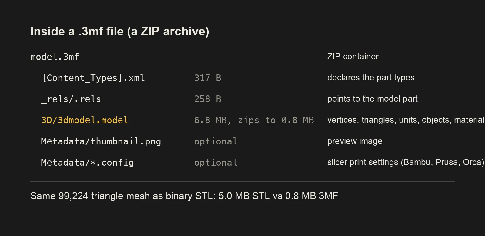
The archive follows a package structure with content types and relationships connecting its parts. A typical package contains [Content_Types].xml, _rels/.rels and a model part such as 3D/3dmodel.model. The model part is XML: readable tags and values describe the mesh and its resources. The exact filenames can vary because relationships identify the model. Treat the familiar directory layout as a useful example, and keep the package relationships intact when inspecting it.
Within a mesh, vertices form a numbered list and each triangle refers to three entries in that list. Adjacent triangles can share a vertex reference. That structure avoids writing a complete set of corner coordinates for every face. The model also has a build description identifying which objects belong in the output and how they are transformed. One stored mesh can support several placed instances, which is useful for a tray full of identical clips.
XML looks verbose when expanded, but its repeated tags and numeric patterns compress well inside ZIP. In the sphere example, roughly 6.8 MB of model XML fits into a package around 0.8 MB. The same geometry occupies about 5.0 MB as binary STL. Those figures describe one mesh and one serialization choice. Texture images, extra plates, configuration files and different numeric precision can all change the balance for another 3MF.
What a .3mf File Type Can Carry
The basic manufacturing information includes mesh geometry, a declared unit, multiple objects and transformations. Names and metadata can make a file easier to navigate, and a thumbnail can show the intended model before you open it. A home slicer usually understands the ordinary mesh and its scale. It may also preserve object names and placement. Those are the features to rely on first when you move a generic file between applications.
Colour and material information can describe the appearance or assignment of different regions. The materials and properties extension supports richer appearance data, including texture resources. A colour-capable manufacturing workflow may use that information directly. A desktop filament slicer often expects its own painting data or part-to-filament assignments, so a textured surface does not automatically become a printable multi-colour job. Check the material list and the sliced tool changes after import.
A slicer project can add printer profiles, layer settings, support choices, plate organization and other application data to the package. These additions make saving and reopening your own work convenient. They can also create a misleading expectation when you send the project elsewhere: the receiving slicer may recover the geometry while ignoring a profile it does not recognize. Confirm both the machine selection and the actual process settings before using a shared project.
Specialized extensions serve manufacturing tasks beyond an ordinary home print. The beam lattice extension describes structures built from beams, while the production extension supports identification and organization of parts across a production workflow. Their presence in the format does not establish support in a home slicer. Ask whether the application reads that extension, and obtain an ordinary mesh export when its specialized representation cannot be used at the destination.
What Is an STL File?
An STL file describes the surface of an object as a collection of triangles. Each triangle records three corner positions and a surface normal. Together those faces approximate the boundary of the part. A slicer reads that boundary, finds cross-sections at successive heights and generates the walls, infill and support paths that the printer will follow. The file itself contains no layer plan or instruction to heat a nozzle.
A cube needs only a few triangles to represent its flat faces. A smooth sphere needs many more because each triangle is flat and the collection only approximates a curve. This makes export resolution important. Too few faces can leave visible facets around a cylinder; an excessive number makes the file and processing heavier with little benefit at the intended print size. The same tradeoff applies when those triangles are saved inside 3MF.
STL became widespread through early stereolithography systems and has remained a common exchange format since the late 1980s. Its long use explains why old CAD programs, model libraries, repair utilities and current slicers tend to support it. When you need to send one uncoloured part to an unfamiliar recipient, binary STL is the safe choice. Include the intended dimensions because the format provides no standard unit declaration.
The STL File Format: Triangles and Nothing Else
STL has two common encodings. ASCII STL writes facets and coordinates as text, with words identifying each normal, loop and vertex. Binary STL writes fixed-size numeric records. They can describe the same triangles, but the binary version is usually much smaller and faster to move around. Choose binary when an export dialog offers both and the receiving tool accepts it. ASCII is useful when a person or a simple text-processing tool needs to inspect the coordinates.
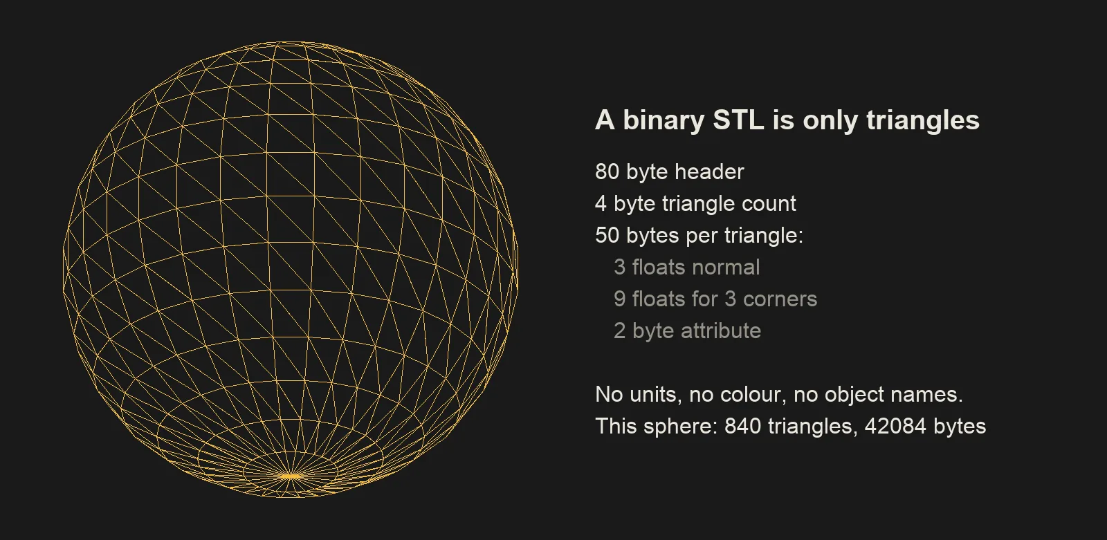
A binary STL starts with an 80 byte header followed by a 4 byte triangle count. Each triangle then uses 50 bytes: 12 for its normal, 36 for three vertex coordinates and 2 for an attribute field. The ordinary interoperable meaning is geometry. Some nonstandard variants use the attribute field for colour, with incompatible conventions. Do not depend on those variants to move material assignments between slicers; a plain STL workflow should assume that colour is absent.
The unit problem comes from storing coordinate numbers without saying what they measure. An edge running from 0 to 25.4 could mean millimetres, inches or another convention chosen by the exporter. Most desktop slicer workflows expect millimetres, so an inch-based export can appear 25.4 times too small. Set the export unit deliberately and measure one known edge on import. A plausible-looking preview is a weak check when the viewer automatically fits every model to its window.
The format's beginnings are commonly associated with 1987, while its early specification is dated 1988. That history helps explain a design centered on transmitting a triangulated surface. Adjacent faces repeat the coordinates of shared corners because each facet is written as an independent record. There is no shared vertex table linking them together. This redundancy is simple to parse, but it increases storage as the triangle count rises.
Why STL Files Are So Large
Binary STL size follows a direct formula: 84 + 50 x the number of triangles, in bytes. A model with 100,000 triangles uses about 5.0 MB, one with 500,000 uses about 25 MB, and one with 2,000,000 uses about 100 MB. Those are decimal megabytes. A file manager using a binary size unit may display a different number for the same byte count, so compare the bytes when you need an exact answer.
The size is driven by tessellation, not by the object's real-world dimensions. A tiny sculpted face can contain more triangles than a large storage box. Repeatedly subdividing a surface can add records without adding useful printed detail, and exporting a CAD curve at very fine tolerance can create many small facets. Before reducing the mesh, identify which curves, holes and embossed features need to retain their shape at the final scale.
ASCII STL grows further because every number becomes a string of characters surrounded by repeated keywords. Decimal precision and whitespace affect its size, so there is no universal bytes-per-face figure for the text form. In the examples below, 99,224 triangles occupy 16.72 MB as ASCII STL and 4.96 MB as binary STL. Both can represent the same surface; the larger text file does not establish higher quality.
3MF saves space through indexed geometry and ZIP compression. At 9,800 triangles, the measured sphere files are 490 KB for binary STL, 1.65 MB for ASCII STL and 70 KB for 3MF. At 499,848 triangles, they are 24.99 MB, 84.23 MB and 4.20 MB. These examples show the effect on regular mesh data. Irregular coordinates, embedded textures and extra project resources can produce different compression ratios.
Computed from the binary STL layout: 84 bytes of header plus 50 bytes per triangle. The Opolyo generator's face limit runs from 500 to 2,000,000, so the largest export sits at the right edge of this chart.
Measured 2026-09-22 on a UV sphere of 99,224 triangles written by the same script. At 499,848 triangles the files are 24.99 MB, 84.23 MB and 4.20 MB.
How to Convert 3MF to STL and STL to 3MF
Conversion should preserve the surface you need and make any lost information explicit. Going from 3MF to STL removes the standard place for units, appearance resources, object identities and project settings. Going from STL to 3MF creates a container that can hold those properties, but you still have to supply them. The converter cannot recover the intended unit, colour or printer profile from triangle coordinates alone.
Use a slicer when the source is a printing project and you want to choose which plate or object to export. Use the Opolyo workspace when you already have a supported model and need a manufacturing export from it. A generic conversion is a geometry task. Keep a separate copy of a configured project so support choices, material assignments and other preparation remain available for the next print.
The five checks below work in both directions. Record the original dimensions and triangle count before you start, especially for an assembly or a detailed generated figure. A successful export dialog only confirms that a file was written. Reopening that file in a fresh session confirms what the next application will actually receive, including its scale, separate pieces and visible surface.
Open the model in a slicer or Opolyo
For a 3MF project, open it in the slicer that created it when possible. Inspect the plate list and select the part or assembly you need. Bambu Studio, PrusaSlicer, OrcaSlicer and Cura support common model imports, although their project handling and export commands differ. If an import dialog offers project loading or geometry-only loading, choose according to whether you want the saved configuration to enter the session.
For a GLB starting point, the GLB to STL converter provides a browser route to a plain mesh. The OBJ to STL converter serves the same purpose for OBJ geometry. Use the Opolyo workspace for 3MF output and other supported export targets. Before proceeding, rotate the imported model and check that its base, accessories and small detached pieces are all present.
Check units and one known dimension
Read the model dimensions in the destination application. For STL, confirm the intended unit with the source or a known measurement, then set the physical size explicitly. For 3MF, confirm that the declared unit and any object transforms have been interpreted correctly. A 40 mm wide lid should still measure 40 mm across after import; matching the visual proportions alone cannot catch a uniform scale error.
Scale an assembly as a group when its pieces must fit together. Scaling only the body while leaving a lid or locating pin unchanged breaks that relationship. If you are converting an asset with no manufacturing dimensions, choose its intended print height and inspect the thinnest feature at that height. A decorative antenna that looks substantial on screen may become too narrow to form in the sliced job.
Export the required format
Choose binary STL for a compact geometry-only export. Choose generic 3MF when you want a mesh with explicit units and supported object information. Save a slicer project as 3MF when your objective includes its printing configuration. Read whether the command exports the selection, current plate or full project, and use a new filename that identifies the intended size or plate.
If the next editor needs OBJ, the STL to OBJ converter can make that geometry available in an OBJ container. That conversion does not restore texture coordinates, colour or modeling history that the STL never held. Likewise, saving STL as 3MF does not add painted regions by itself. Add those properties in an application that supports them, then save the enriched project separately.
Verify the triangle count and surface
Reopen the exported file and compare its triangle count with the source selection. A pure mesh format conversion should normally keep the same triangles, with possible differences from repair or exporter behavior. A large count change deserves inspection: you may have exported only one object, included extra copies, applied a simplification setting or baked a modifier. Compare dimensions and separate shell counts as well.
Triangle count is only one check. Two meshes can have the same number of faces and different coordinates, and one exporter may expand instances into separate meshes. Inspect the silhouette, holes and flat base, then slice with your own printer profile. Move through the preview around narrow areas and intersections to confirm that the resulting walls match the intended part.
Keep the original with the converted copy
Retain the original 3MF project if you exported STL, and retain the original textured GLB if you exported a manufacturing mesh. Use distinct names so a geometry-only copy cannot overwrite the version holding materials or configuration. Keep a native CAD file too when one exists, because neither STL nor an ordinary mesh-based 3MF preserves the original parametric design history.
For a file you plan to share, include the intended size and explain whether the 3MF is generic or tied to a slicer project. Reopen the final copy once without relying on the existing session. This catches a common mistake in which the application still displays unsaved settings and makes an incomplete export look more complete than it is.
Converting in the Slicer
Bambu Studio, PrusaSlicer, OrcaSlicer and Cura can bring STL and ordinary 3MF geometry into a print workflow. Their menus distinguish several operations that can look similar: opening a project, importing a model, exporting a mesh and exporting a sliced job. For conversion, start from the model or project and choose a model export. A print export can produce machine instructions that no longer provide an editable replacement for the source mesh.
For 3MF to STL, open the source and select the desired model or plate. Export STL through the available mesh export command, then open the result as a new object. Colour assignments, named object relationships and printer settings cannot travel in a standard STL. Geometry can still retain the visible shape, including separate shells, but the receiving application may group those shells differently. Check that a model sitting above the plate was placed as intended after the export.
For STL to 3MF, import the STL, confirm dimensions and save or export the appropriate 3MF. A project save can include the slicer's current settings; a generic model export focuses on transferable geometry. Cura's project workflow and the project commands in the other slicers need their own interpretation, so read the export type shown in the dialog. If your version lacks a particular mesh export, use a compatible model conversion tool for that step.
A cross-slicer handoff needs an extra review even when both applications accept .3mf. Support painting, modifiers, material mappings and printer presets may use application-specific data. The target may offer to import geometry alone or warn that some configuration is unsupported. After import, select the actual printer and nozzle, assign available materials and inspect support placement. Save a new project from the receiving slicer once the configuration matches your machine.
Converting an AI Generated Model to 3MF or STL
The Opolyo image to 3D generator starts from one JPG, PNG or WEBP up to 10 MB and produces a GLB in the workspace. A generation with Standard textures costs 10 credits. The workspace converter can write FBX, OBJ, STL, glTF, USDZ and 3MF from that model. Choose STL or 3MF for a slicer, and keep the original GLB when you also want the textured digital asset.
An image supplies visible appearance and shape cues, so the generated back and hidden surfaces need inspection. Rotate the bare mesh before choosing a print size. Check the underside, narrow limbs, accessories and any opening that should pass through the model. The texture can suggest grooves or small details that are absent from the actual geometry. Switching to an untextured view shows which features a geometry-based print can reproduce.
A model created through text to 3D needs the same downstream checks for a print. Establish a physical height, confirm that the smallest important parts remain printable at that height, and select the export format that your slicer uses. A format conversion changes how the mesh is stored. Geometry editing, remeshing or a change in size is a separate decision with its own effect on the final object.
The dwarf below contains 820,770 triangles and occupies 24.5 MB as a GLB with three textures. Its binary STL geometry alone is about 41 MB because STL repeats per-face coordinates. That larger file has discarded the texture resources; file size therefore cannot tell you how much appearance information survived. A compressed 3MF can keep the mesh with an explicit unit, while texture and material transfer still depend on the export and the receiving application.
Convert a model to 3MF or STL
Upload a GLB, OBJ or STL you already have, or generate one from a picture, then write it out as 3MF or STL. A basic conversion costs 2 credits; Standard texture generation costs 10.
3MF vs STL Compared Feature by Feature
STL and 3MF overlap at the mesh. Given the same triangles, dimensions and slicing settings, either can lead to the same printed surface. The differences concern what can accompany that surface and how the data is packaged. Use the comparison to identify what your handoff needs: universal access to a plain mesh, an explicit unit, separate objects, appearance information or the state of a prepared slicer project.
A capability in the 3MF column means the format or its extensions can carry that information. Your exporter must write it and the receiving application must understand it. A generic 3MF may have no print settings at all, while a slicer project may include configuration another slicer ignores. For a shared job, agree on the destination application and inspect the imported object list and settings before assuming the project is ready to print.
| Feature | STL | 3MF |
|---|---|---|
| Geometry | Independent triangle records describing a surface | Indexed triangle meshes with object and build structure |
| Units | No standard unit field; millimetres are a common slicer convention | Explicit model units; confirm the importer respects them |
| Colour and materials | No interoperable standard colour or material data | Supported through resources and extensions; application support varies |
| Multiple objects | Several shells can share a file without structured object identity | Separate objects, components and placed instances |
| Print settings | Absent; save them separately in a slicer project | Slicer projects can include settings, often specific to that application |
| Textures | No standard texture resources or UV coordinates | Texture resources through supported extensions and exporters |
| File size | Binary: 84 + 50 x triangle count bytes; ASCII usually larger | Often smaller for the same mesh; resources and compression affect size |
| Compression | No built-in compression; an external archive is separate | ZIP package compression |
| Metadata and author | No standard structured author or descriptive metadata | Metadata fields can carry descriptive information |
| Thumbnail | No standard embedded thumbnail | Optional thumbnail resource |
| Year introduced | 1987 | 2015 |
| Who maintains it | Nobody; legacy format with established conventions | 3MF Consortium under the Linux Foundation |
| Slicer support | Very broad, including older tools | Broad core mesh support in modern slicers; project features vary |
| Download site support | Widely accepted for simple model distribution | Common for projects and multi-part files; acceptance varies by site |
| CAD export support | Widely available across CAD and mesh tools | Available in supporting tools; check the exporter and version |
When STL Is Still the Right Choice
STL is useful when the recipient needs one uncoloured surface and will choose their own printing settings. A spacer, hook, replacement knob or simple enclosure can travel as a binary STL with an intended dimension in the accompanying description. The recipient can select their own printer, orientation, supports and material. There is little project information to preserve when none of those decisions should be shared in the first place.
It is also practical for older software, limited import dialogs and workflows with an explicit STL requirement. A service bureau or school lab may ask for STL because its intake process is built around that format. Follow the destination's instructions, use a sensible export tolerance and confirm the unit convention. If the same design is available in several formats, the one the receiving workflow already handles reliably can save a needless conversion step.
A public download benefits from predictable geometry access. Providing STL lets many readers load a part without importing an unfamiliar printer profile. You can still offer a 3MF project alongside it for people who want your plate arrangement or painting. Name the files clearly and describe which machine and material the project expects. A bare mesh and a prepared project answer different needs within the same model listing.
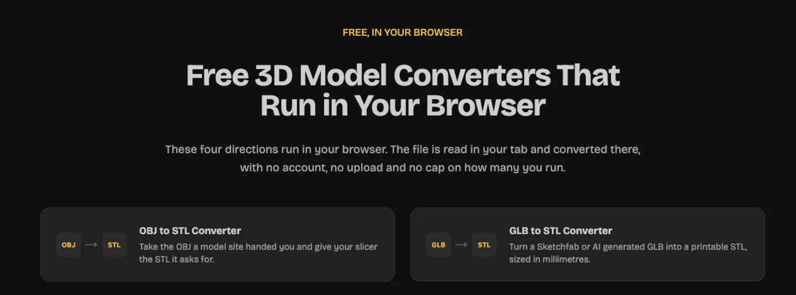
The browser converters are useful for an existing asset that only needs a format change. Opolyo provides four browser directions: GLB to STL, OBJ to STL, STL to OBJ and FBX to OBJ. They run without an account and keep the file in the browser tab. STL output uses millimetres. The workspace handles 3MF output, so choose that route when the manufacturing container itself is part of your requirement.
When to Use 3MF for 3D Printing
Use 3MF when the file needs to say more than where the surface lies. Units are useful even for a single plain object, while multiple objects and placement become valuable for assemblies and organized plates. A slicer project can keep the choices that made a difficult print work: orientation, supports, modifiers and material assignments. Saving that project lets you return to the prepared state without rebuilding it from a folder of meshes.
A practical example is a two-part sign with a base and raised lettering. The meshes need a shared alignment, and the letters may use a second filament. A suitable 3MF project can retain the relationship and assignments in one package. If you export both shapes as separate STL files, the receiver needs enough information to reconstruct their relative positions and decide which material belongs to each. Either route can work, but the preparation burden differs.
3MF also helps when the model is large on disk. A compressed mesh can be easier to store, attach or download than its binary STL equivalent. That advantage concerns the package size, so keep expectations about slicing time separate. A dense figure remains a dense figure after decompression, and a project containing several copies may still require substantial processing even when the archive is small.
Multi-Colour and Multi-Object Prints
Multi-object and multi-colour describe different properties. A plate can contain six identical single-colour clips, while one continuous figurine can have several painted regions. 3MF can organize objects and can carry appearance or assignment information, but the slicer has to translate the relevant data into a printable job. Start by checking the object tree, then check the material assignments. Seeing several colours in a shaded preview does not establish that the printer will perform the expected changes.
For separate parts that fit together, preserve their common coordinate relationship when it matters. A two-colour logo may need letters registered precisely over a backing plate. Importing separate STLs as unrelated objects can cause a slicer to arrange each one independently. A multi-part object or a compatible 3MF assembly can retain alignment. Confirm that the application has kept the components together before moving the assembly onto the bed.
A desktop filament workflow also needs real materials assigned to available tools or feed positions. Project colours can be labels for those assignments, while texture pixels describe a surface appearance that may have no direct filament equivalent. Review the available spools, map each region deliberately and inspect the sliced tool changes. A colour that has no assigned material may be ignored, mapped unexpectedly or require manual work, depending on the application.
How to Get a 3MF File From Bambu Studio
In Bambu Studio, use File, Export and the relevant 3MF command for the output you need. Export plate as 3MF focuses on the plate workflow, while Export generic 3MF provides a more general model handoff; the available wording and scope can depend on the version and current selection. Check which plate and objects are included before saving. If you want to resume the whole editing session, use the project save command and retain that project separately from any exported delivery copy.
A project 3MF can contain Bambu Studio configuration, plate arrangement and material information in addition to geometry. A generic 3MF is intended for broader model exchange and should be treated according to the geometry and properties that actually survive import in the receiving application. Reopen the exported copy to confirm the distinction. For a recipient using another slicer, state whether you are sending a configured project or generic meshes, and include the intended dimensions when the physical fit matters.
After slicing, a printer job may be exported or sent as gcode.3mf. This package contains the prepared machine instructions and associated job resources for the target printer. Keep it separate from the editable project: changing layer height, material or model geometry requires returning to the model and slicing again. Before sending a shared job to a machine, confirm the printer model, nozzle and material setup. A filename ending in 3mf can identify several stages of the workflow, so read the full name and the export command that produced it.
- What is a 3MF file1,480 searches26%
- What is an STL file1,300 searches23%
- 3MF vs STL1,310 searches23%
- Convert between them1,090 searches19%
- Get a 3MF from Bambu Studio590 searches10%
Monthly US searches, Semrush, read 2026-08-21. Definitions and the comparison itself are asked far more often than conversion.
3D Printer File Formats Beyond STL and 3MF
A 3D printing workflow can begin with several kinds of source file. CAD documents preserve design operations and dimensions, mesh formats describe surfaces, scene formats carry appearance and organization, and sliced files describe a machine job. The extension helps identify the stage. Choose an exchange format according to what the next application needs to do with the asset, then keep the richer source for future changes.
OBJ, GLB, glTF and FBX often appear when a model comes from an artist, a digital asset library or a generator. They can carry information useful for rendering that a basic print does not use. A conversion to STL extracts a triangulated surface; a conversion to 3MF can package manufacturing geometry with supported properties. Neither operation automatically turns visual shading details into raised or recessed geometry.
For a mechanical design, keep the native CAD document or another suitable editable design source alongside the print mesh. For a textured figure, keep its original asset and image resources. The guide to designing your own 3D prints covers the modeling and printability decisions that come before export. Selecting a container is one part of preparing a usable object.
OBJ vs STL
OBJ describes a mesh using vertex lists and face references, with support for elements such as texture coordinates, normals, groups and material references. An OBJ can depend on an accompanying MTL file and texture images for its appearance. If you receive only the OBJ, the surface may load correctly while the materials are missing. Keep the related files together when the goal includes editing or viewing the textured asset.
STL is simpler for a plain triangulated printing surface. Exporting OBJ to STL discards texture coordinates and material references, and polygon faces must become triangles. Check concave faces and thin areas after conversion because triangulation can expose problems hidden by a shaded preview. Also confirm physical dimensions: an OBJ workflow needs a clear unit convention, and a plain STL cannot communicate one through a standard field.
GLB vs glTF
glTF describes a scene using JSON and associated resources. A .gltf file commonly references separate binary buffers and image files, while GLB provides a binary container that can bundle the scene description and resources. They belong to the same format family. GLB is convenient for moving a self-contained asset; a separated glTF package can make individual resources easier to inspect or replace.
For printing, select the visible geometry you intend to manufacture and apply its scene placement consistently during conversion. Check the resulting dimensions and inspect the surface without materials. A normal map can make a flat region look detailed on screen while leaving the mesh unchanged. The AI 3D printing guide covers further checks for generated assets before they enter a slicer.
OBJ vs FBX
OBJ is a common static mesh exchange choice. FBX can carry a broader scene, including hierarchy, animation and other application data, with support depending on the exporter and importer. That extra scene information can matter to an animator or game workflow. A slicer usually needs a static surface at a specific physical scale, so decide which pose and which objects should become the print before exporting a mesh.
Opolyo includes FBX among the workspace export targets, and its browser FBX to OBJ direction can serve a static mesh handoff. Select the destination based on the receiving application's requirements. For a print, continue to a supported STL or 3MF workflow and verify dimensions after each format boundary. Animation data and rendering materials do not supply the manufacturing decisions needed for walls, support placement and layer planning.
What File Format Do 3D Printers Actually Use?
Many filament printers execute G-code or a machine-specific package containing it. G-code describes actions such as movement, extrusion and temperature changes. STL and ordinary model 3MF describe the object before those actions have been planned. The slicer performs the essential conversion: it combines the model with a printer profile, material choices and process settings to produce the job that the machine can run.
This is why changing a filename from .stl to .gcode cannot make a printable job. Slicing has to calculate layers, perimeter paths, infill, support, travel and the machine's start and finish behavior. A model file lacks those instructions. Select the exact printer and nozzle configuration, choose the material and inspect the preview before saving the sliced output in the format your machine accepts.
Bambu's gcode.3mf packages a sliced job and associated resources. It shares the archive extension with model and project files, which can make downloads confusing. Read the full filename and identify whether the file opens as editable geometry or as a prepared job. Preserve the project when you may need another layer height or printer configuration, because the prepared toolpaths cannot serve as a full replacement for the source model.
Resin printers commonly use machine-specific sliced formats containing layer images and exposure-related information. Their input to the slicer can still be STL or 3MF where supported. In either process, use the printer's accepted output format and generate it for that machine. Sharing a mesh gives the recipient control over slicing; sharing a finished job also transfers assumptions about hardware, material and process settings.
Opening and Editing 3MF Files
Open a 3MF in a compatible slicer when you want to print it or inspect a saved project. Bambu Studio, PrusaSlicer, OrcaSlicer and Cura handle common 3MF model workflows, with different levels of project compatibility. Read any prompt about importing a complete project or only its geometry. Then inspect dimensions, objects and selected printer settings before editing or slicing.
Windows 3D Viewer can display supported 3MF models on systems where it is installed. A viewer is useful for rotating the surface and checking the contents visually, but it does not replace a slicer for inspecting the actual layers. Fusion 360 provides mesh workflows for supported imports, while Blender may need a compatible 3MF import add-on. Confirm support in your installed version and keep the original package before any round trip through another application.
Editing can mean changing placement, changing printer settings or changing the surface itself. A slicer usually handles scale, orientation, cuts and project configuration. A mesh editor provides more control over vertices and local shape. For a dimensioned mechanical revision, return to the native CAD source when available. A triangulated 3MF does not recreate the original sketches, constraints and feature history simply because its container carries more metadata.
You can also open a copy as a ZIP archive and read the XML to inspect units, object definitions and relationships. This helps explain what is inside a file whose name gives little context. Preserve its folder structure and resource references if you edit the package directly. After any change, reopen it in the intended application and check geometry and layers; a readable archive can still contain invalid model relationships or an unintended surface.
What Converting to 3MF Costs on Opolyo
A basic workspace conversion on Opolyo costs 2 credits. An advanced conversion costs 3 credits and covers options such as quad remesh, face limit, UV packing and flatten bottom. Uploads of your own model can be up to 100 MB. Use basic conversion when the surface is already suitable and the task is changing the file format; choose the relevant advanced controls when you also need a supported geometry or layout operation.
Image to 3D with Standard textures costs 10 credits and produces a GLB in the workspace. The input is one JPG, PNG or WEBP up to 10 MB. Generation and workspace conversion are separate operations: a Standard generation followed by one basic conversion totals 12 credits. Keep the generated source so another export can start from the same model without creating the shape again.
Plans start at $19.99 per month, and a one-time credit pack is available. The pricing page lists the plan and credit options. For an existing GLB or OBJ that only needs STL, the browser converters provide that direction without an account or upload. For 3MF output, use the workspace conversion route and choose the settings that match the required result.
Get the file your slicer wants
Generate a model from one picture for 10 credits, then export STL or 3MF from the same workspace. Plans start at $19.99 per month.
Already have a GLB or OBJ?
Convert it to STL in the browser. No account, no upload, the file never leaves your machine.
3MF vs STL FAQ
A 3MF file is a compressed manufacturing package that can contain mesh geometry, physical units and multiple objects. Supported resources and extensions can add colour, materials and other information. A slicer project can also save application-specific print settings in the package.
An STL file describes an object's surface with triangles. It comes in binary and ASCII forms and has no standard unit, texture or print-setting fields. A slicer turns that surface into layers and machine instructions.
3MF is more useful when you need explicit units, several objects or a compatible saved print project. STL remains useful for a simple mesh going to a broad range of software. The same triangles can produce the same print in either format when scale and slicing settings match.
You can preserve the mesh geometry in a suitable conversion, but standard STL cannot carry the full contents of a rich 3MF. Units, colour, object identities and project settings can be lost. Keep the original and compare dimensions and geometry after export.
Import the STL into a compatible slicer or converter and confirm its physical dimensions. Export generic 3MF for a model handoff or save a 3MF project to retain supported slicer settings. Colour and configuration must be supplied separately because the STL does not contain them.
Many filament printers use G-code or a package containing prepared machine instructions. Resin printers commonly use machine-specific sliced layer formats. A slicer converts STL or supported 3MF geometry into the output required by the selected printer.
Use File, Export and choose Export plate as 3MF or Export generic 3MF as appropriate for your version and intended output. Use the project save command when you want to retain the editable project configuration. Reopen the saved copy to confirm which objects and settings it contains.
Open it in a compatible slicer such as Bambu Studio, PrusaSlicer, OrcaSlicer or Cura. Supported viewers can display the model, and an archive utility can expose the XML inside a copy. Project-specific information may require the application that created it.
Yes, a compatible slicer can change placement, scale and supported project settings. Surface changes may require a mesh editor and an appropriate import route. Keep the original because another application may discard configuration or extensions it does not understand.
Binary STL uses 50 bytes per triangle plus an 84 byte header, so dense meshes grow quickly. ASCII STL usually needs more space to write the same coordinates as text. Binary export or 3MF compression can reduce storage, while reducing triangles changes the actual geometry workload.
Standard interoperable STL does not provide colour or texture data. Some binary variants use incompatible colour conventions, so they are unreliable for general exchange. Use a supported 3MF workflow or assign materials in the slicer when colour matters.
It is a package containing a sliced printer job and associated resources in workflows such as Bambu Studio. It belongs to the machine-output stage and should be kept separate from the editable model project. Changes to geometry or printing settings normally require slicing the source again.
A compatible 3MF project is useful for preserving plates, material assignments and print configuration. STL is sufficient for importing a plain mesh and preparing your own settings. Review the selected printer, nozzle and materials when opening someone else's project.
Yes, 3MF is a workspace converter export target alongside FBX, OBJ, STL, glTF and USDZ. Basic conversion costs 2 credits and advanced conversion costs 3 credits. Image to 3D with Standard textures is a separate 10 credit generation that produces a GLB source.
Sources and References
- 3MF Consortium, 3MF core specification (accessed 2026-09-22)
- STL (file format), Wikipedia (accessed 2026-09-22)
- Khronos Group, glTF overview (accessed 2026-09-22)
- 3MF Consortium, About (accessed 2026-09-22)
- Wavefront .obj file, Wikipedia (accessed 2026-09-22)
Move the file where it needs to go
Opolyo user
Jaxon uses Opolyo for his own models and writes about what he runs, on the same plans and the same credits as everyone else.
Export the format your printer wants
Generate from one picture, then write out STL or 3MF from the same workspace.